Rockwell Automation Publication 825-UM004D-EN-P - November 2012 27
Installation Chapter 2
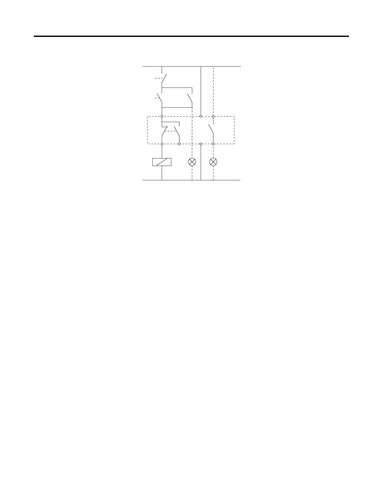
Figure 16 - Control Connections for a Full-voltage Non-reversing Starter
NOTE: For AUX1 to work as an alarm/warning indicator, it must be mapped to the “Warning”
function bit.
S0
S1 K1
K1
A1
H1 H3
A2
[
[
TR AUX1
95 A1 13
825-P
96 98 A2 14
Contactor
On push button
Off push button
Indicator "Contactor Closed"
Trip relay
Indicator "Alarm/Warning"
Alarm relay
K1
S1
S0
H1
TR
H3
AUX1
NOTE: For AUX1 to work as an
alarm/warning indicator,
it must be mapped to the
"Warning" function bit.

 Loading...