Rockwell Automation Publication 825-UM004D-EN-P - November 2012 19
Installation Chapter 2
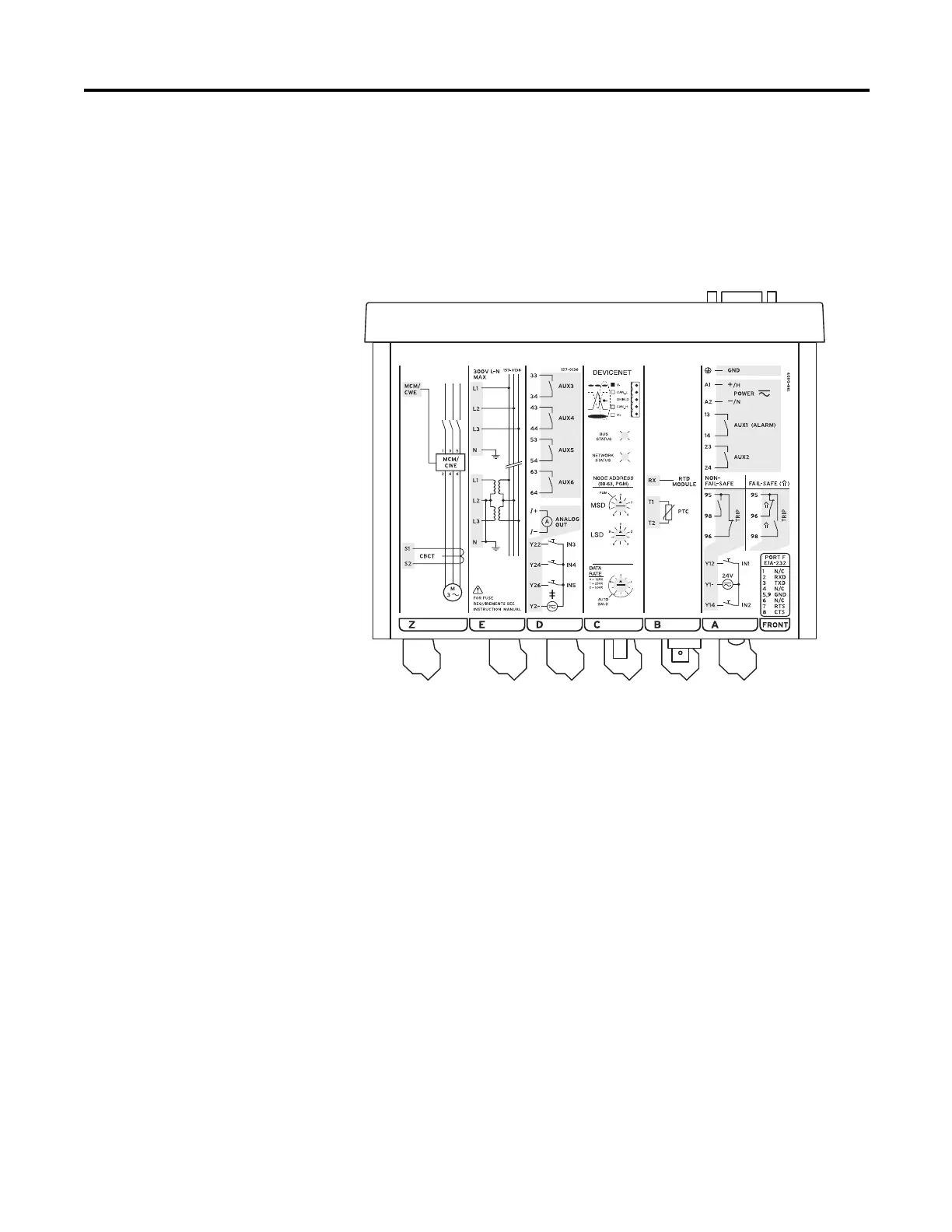
Top-Panel Diagram
The input and output designations for the rear-panel connectors of a fully
configured 825-P are shown in Figure 4. This diagram is located on the top panel
of the relay.
Figure 4 - Top-Panel Input and Output Designations
Power Connections
The power terminals on the rear panel (A1+ and A2-) must connect to
110…240V AC or 110…250V DC for the 825-PD and 24…48V DC for the 825-
PZ. For complete power input specifications, see Appendix:A Specifications.
The power terminals are isolated from the chassis ground. Use 16 AWG
(1.5 mm
2
) size or heavier wire to connect to the POWER terminals. Connection
to external power must comply with IEC 947-1 and IEC 947-3. Place an external
switch, circuit breaker, or overcurrent device in the power leads for the 825-P;
this device must interrupt both the positive (A1+)and neutral (A2-) power leads.
The maximum current rating for the power disconnect circuit breaker or
overcurrent device (fuse) must be 20 A. Be sure to locate this device within 3.0 m
(9.8 ft.) of the relay.
Operational power is internally fused by power supply fuse. See Field
Serviceability on page31 for details. Be sure to use fuses that comply with
IEC 127-2.
‡ See documentation for input voltage rating.

 Loading...