Rockwell Automation Publication 825-UM004D-EN-P - November 2012 17
Chapter 2
Installation
Relay Placement
Proper placement of the 825-P Motor Relay helps make certain that you receive
years of trouble-free motor protection. Use the following guidelines for proper
physical installation of the 825-P.
Physical Location
You can mount the 825-P in a sheltered indoor environment (a building or an
enclosed cabinet) that does not exceed the temperature and humidity ratings
for the relay. The relay can be mounted indoors or in an outdoor (extended)
enclosure where the relay is protected against exposure to direct sunlight,
precipitation, and full wind pressure, but neither temperature nor humidity
are controlled.
Refer to Appendix:A Specifications for environmental ratings.
Relay Mounting
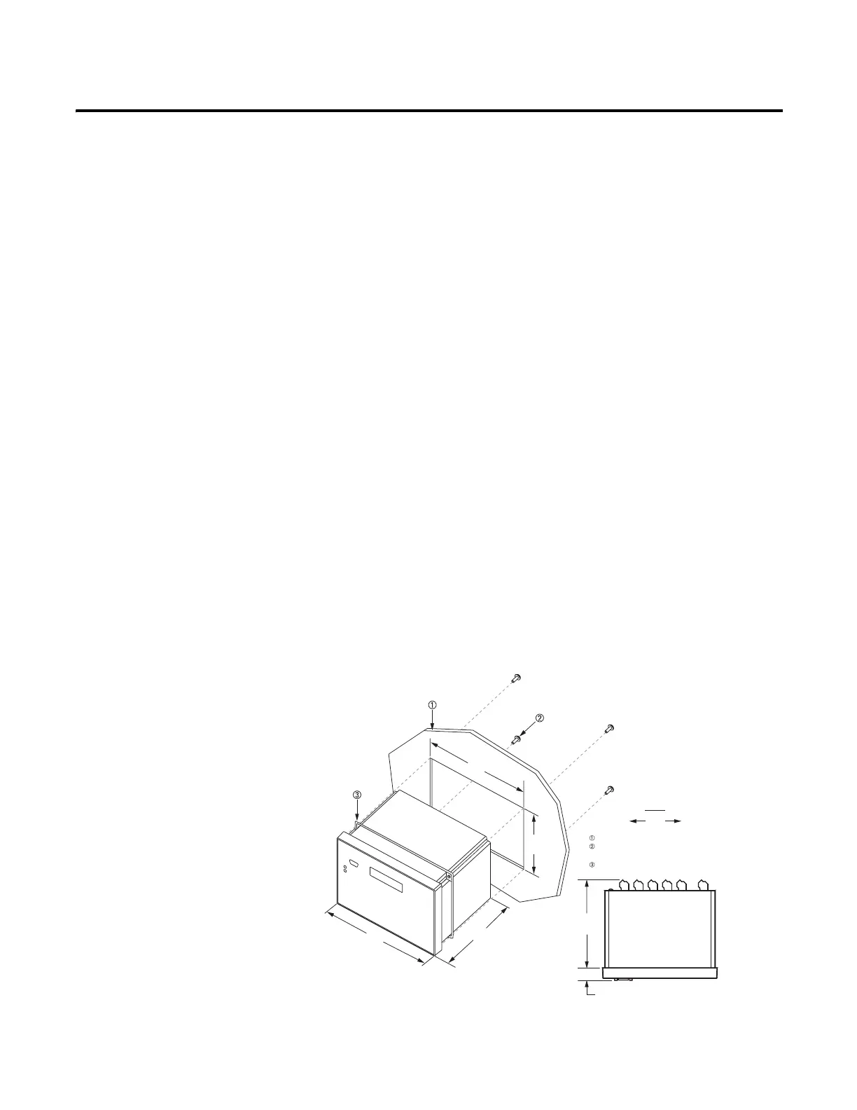
To flush mount the 825-P in a panel, cut a rectangular hole with the dimensions
shown in Figure 2.
Figure 2 - Relay Mounted In a Panel
20.8
(0.82)
147.4
(5.80)
Legend
mm
(in)
192.0
(7.56)
186.0
(7.32)
138.0
(5.43)
144.0
(5.67)
Mounting Panel–maximum thickness 6.5 mm
#8 x 1/2 inch mounting screw;
Torque specication = 0.9...1.3 N
.m (8...12 Lb-in)
Gasket

 Loading...