Rockwell Automation Publication 2198-UM002G-EN-P - February 2019 101
Connector Data and Feature Descriptions Chapter 4
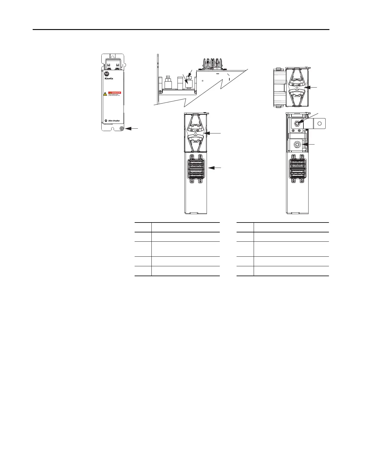
Figure 62 - Extension Module Features and Indicators
2198-CAPMOD-DCBUS-IO
Extension Module
(side view, lug cover removed)
2198-CAPMOD-DCBUS-IO
Extension Module
(front view)
2198-CAPMOD-DCBUS-IO
Extension Module
(top views)
Item Description Item Description
1 Ground lug 5 DC– M8 stud (external DC-bus)
2 Stud/lug cover with wires
(1)
6
DC+ M8 stud (external DC-bus), shown
with flexible bus-bar
(2)
3 Stud cover without wires 7 M8 hex nut
4 DC-bus (DC) connector 8 Lug spacer
(1) This example shows the lug cover oriented for wires exiting to the left (module is on the far left of drive configuration). Rotate
lug cover 180° when wires exit to the right (module is on the far right of drive configuration).
(2) Flexible bus-bars are included with only the 2198-CAPMOD-DCBUS-IO extension module.
 Loading...


