104 Rockwell Automation Publication 2198-UM002G-EN-P - February 2019
Chapter 4 Connector Data and Feature Descriptions
Single-axis inverters, dual-axis inverters, and the regenerative bus supply have
four configurable digital inputs with fast response times and ten configurable
functions to choose from in the Logix Designer application.
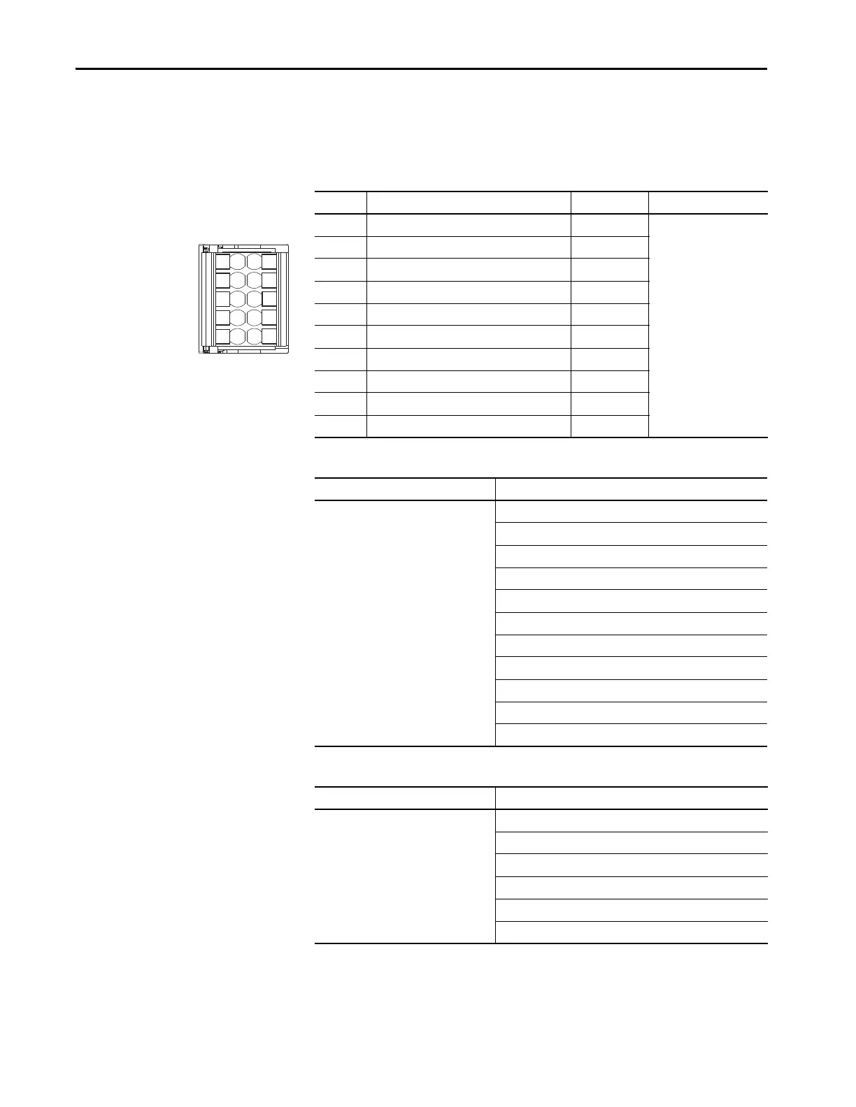
Table 37 - Inverter and Regenerative Bus Supply Digital Input Pinouts
Table 38 - Inverter Configurable Functions
Table 39 - Regenerative Bus Supply Configurable Functions
IOD Pin Description Signal Module
1 24V current sinking fast input #1 IN1
•Inverters
• Regenerative bus supply
2 I/O common for customer-supplied 24V supply COM
3 24V current sinking fast input #2 IN2
4 I/O common for customer-supplied 24V supply COM
5 Chassis ground SHLD
6 24V current sinking fast input #3 IN3
7 I/O common for customer-supplied 24V supply COM
8 24V current sinking fast input #4 IN4
9 I/O common for customer-supplied 24V supply COM
10 Chassis ground SHLD
Default Configuration Description
Digital input1 = Enable
Digital input2 = Home
Digital input3 = Registration 1
Digital input4 = Registration 2
Unassigned
Enable
Home
Registration 1
Registration 2
Positive overtravel
Negative overtravel
Regeneration OK
Bus Capacitor OK
Shunt Thermal Switch OK
Bus Conditioner OK
Default Configuration Description
Digital input1 = Enable
Digital input2 = AC Line Contactor OK
Digital input3 = Unassigned
Digital input4 = Unassigned
Unassigned
Enable
Bus Capacitor OK
Shunt Thermal Switch OK
AC Line Contactor OK
Bus Conditioner OK
1
2
3
4
5
6
7
8
9
10
Pin Orientation for 10-pin
Digital Inputs (IOD) Connector
 Loading...


