Rockwell Automation Publication 2198-UM002G-EN-P - February 2019 153
Connect the Kinetix 5700 Drive System Chapter 5
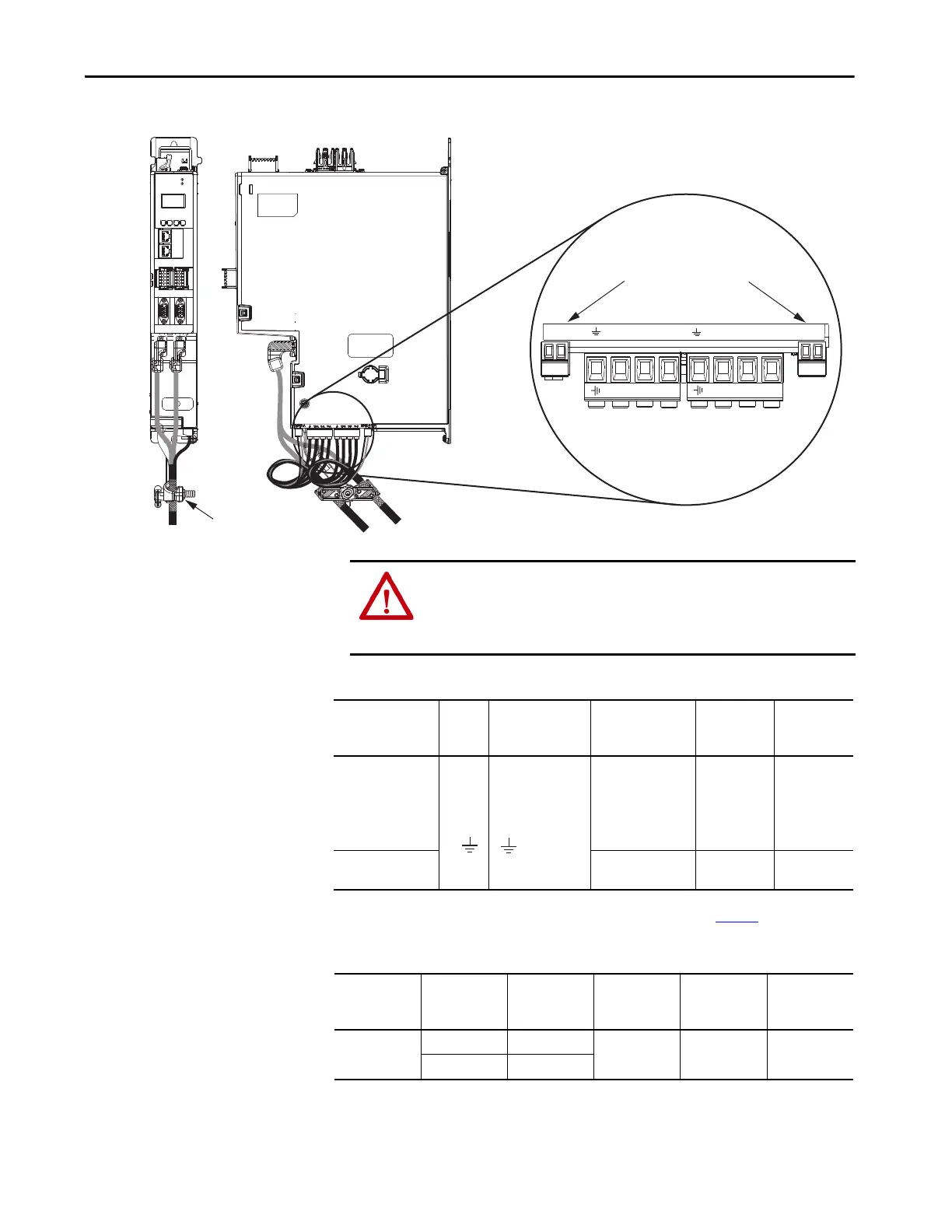
Figure 100 - MP and BC Connector Wiring (dual-axis inverters)
Table 75 - Motor Power (MP) Connector Specifications (dual-axis inverters)
Table 76 - Motor Brake (BC) Connector Specifications
MOD
NET
2
1
1
I/O-A
6
510
1
I/O-B
6
510
UFB-A UFB-B
D+
D-
D+
D-
MF-A MF-B
W-B V-B U-B
MBRK-A
– +
W-A V-A U-A
MBRK-B
– +
2
1
W
V
U
W
V
U
2
1
Motor Cable
Shield Clamp
Motor Power
(MP) Connector Plugs
2198-Dxxx-ERSx
Dual-axis Inverters
(2198-D006-ERS4 drive is shown)
Motor Brake
(BC) Connector Plugs
Bulletin 2090 Motor Power Cable
(2090-CSxM1DE/DG cable is shown)
ATTENTION: Make sure the motor power connections are correct when
wiring the MP connector plug and that the plug is fully engaged in the
module connector. Incorrect wiring/polarity or loose wiring can cause
damage to equipment.
Dual-axis Inverter
Cat. No.
Pin Signal/Wire Color
Recommended
Wire Size
mm
2
(AWG)
Strip Length
mm (in.)
Torque Value
N•m (lb•in)
2198-D006-ERSx
2198-D012-ERSx
2198-D020-ERSx
2198-D032-ERSx
Motor power cable
depends on motor/
drive combination.
0.75…2.5
(1)
(18…14)
10.0 (0.39)
0.5…0.6
(4.4…5.3)
2198-D057-ERSx
2.5…6
(1)
(14…10)
10.0 (0.39)
0.5…0.8
(4.4…7.1)
(1) Building your own cables or using third-party cables with Kinetix VP servo motors is not an option. Use 2090-CSxM1DE/DG single
motor cables. Refer to the Kinetix Motion Accessories Specifications Technical Data, publication KNX-TD004
, for cable specifications.
Brown
Black
Blue
Green/Yellow
U
V
W
Drive Module
Cat. No.
Pin
Signal/
Wire Color
Recommended
Wire Size
(AWG)
Strip Length
mm (in.)
Torque Value
N•m (lb•in)
2198-Dxxx-ERSx
2198-Sxxx-ERSx
BC-1 MBRK+/Black
N/A
(1)
7.0 (0.28)
0.22…0.25
(1.9…2.2)
BC-2 MBRK-/White
(1) Motor brake wires are part of the Bulletin 2090 motor power cable.
 Loading...


