Rockwell Automation Publication 2198-UM002G-EN-P - February 2019 259
Configure and Start the Kinetix 5700 Drive System Chapter 6
4. Enter values for the Digital AqB specification fields.
The only valid value for Cycle Interpolation is 4.
5. From the Startup Method pull-down menu, choose Incremental.
6. Click Apply.
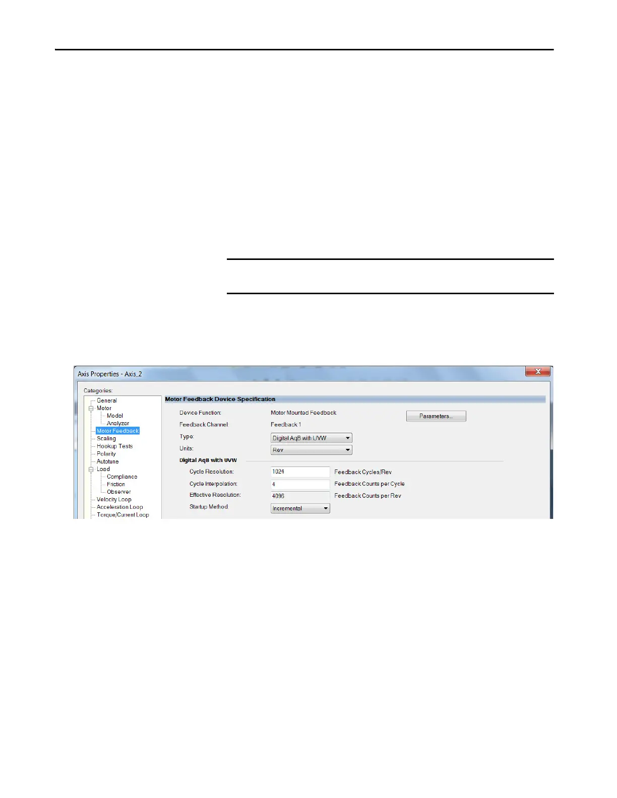
Digital AqB with UVW (TTL w/Hall) Feedback
In this example, a motor feedback device is configured for Digital AqB with
UVW feedback.
1. In the Controller Organizer, right-click an axis and choose Properties.
2. Select the Motor Feedback category.
The Motor Feedback Device Specification dialog box appears.
3. Configure the device function and type.
In this example, Motor Feedback is the device function and Digital AqB
with UVW is the feedback type.
4. Enter values for the Digital AqB with UVW specification fields.
The only valid value for Cycle Interpolation is 4.
5. From the Startup Method pull-down menu, choose Incremental.
6. From the Alignment pull-down menu, choose Not Aligned.
7. Click Apply.
TIP When the Device Function is Load-Side Feedback or Master Feedback,
configuration is identical to Motor Mounted Feedback.
IMPORTANT When Motor Mounted Feedback is the Device Function, Digital AqB with
UVW is the only valid feedback type for permanent magnet motors.
 Loading...


