268 Rockwell Automation Publication 2198-UM002G-EN-P - February 2019
Chapter 6 Configure and Start the Kinetix 5700 Drive System
The Position Units are defined in Axis Properties>Scaling category.
5. Click the desired test to verify connections.
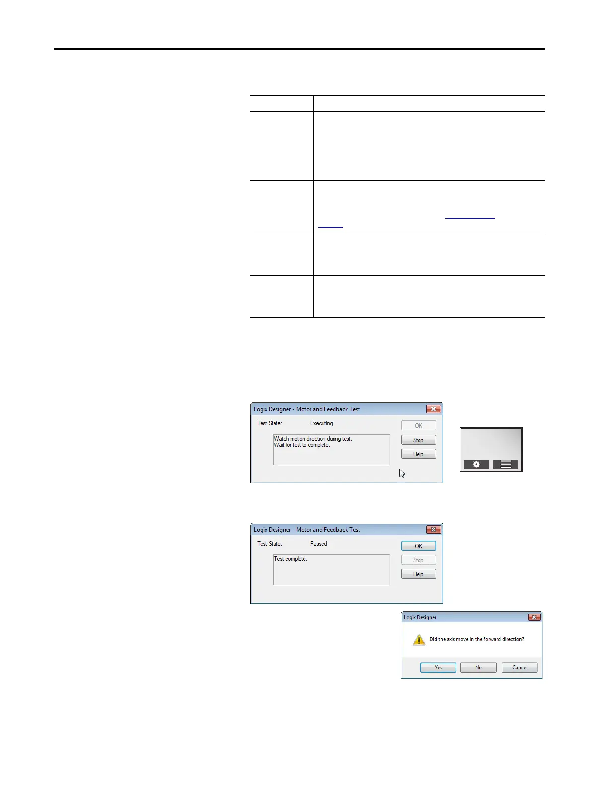
6. Click Start.
The Logix Designer - Motor and Feedback Test dialog box appears. The
Test State is Executing. TESTING appears on the drive LCD display.
When the test completes successfully, the Test State changes from
Executing to Passed.
7. Click OK.
This dialog box appears asking if
the axis moved in the forward
direction.
8. Click Yes if you agree.
9. Click Accept Test Results.
Hookup Test Definitions
Marker
Verifies marker detection capability as you manually rotate the motor shaft. The
test completes when the drive either detects the marker or when the motor moves
the distance specified in the Test Distance field. If the marker remains undetected
and the test completes successfully, it means the motor moved the full test
distance. If the marker remains undetected and the test fails, the motor did not
move the full test distance. Run this test after running the Motor Feedback and
Motor and Feedback tests.
Commutation
Verifies the commutation offset and commutation polarity of the motor. This test
applies to third-party or custom permanent-magnet motors equipped with (TTL
with Hall and Sine/Cosine with Hall) incremental encoders that are not available as
a catalog number in the Motion Database. See Commutation Test on page
page 445.
Motor Feedback
Verifies feedback connections are wired correctly as you manually rotate the motor
shaft. The test completes when the drive determines that the motor moved the
full distance specified in the Test Distance field. Run this test before the Motor and
Feedback Test to verify that the feedback can be read properly.
Motor and Feedback
Verifies motor power and feedback connections are wired correctly as the drive
commands the motor to rotate. Because the drive is rotating the motor, this test
requires full bus power to run. Run the Motor Feedback test before running this
test to verify that the feedback is being read correctly.
TESTING
192.168.1.1
DC BUS: 680.0V
 Loading...


