392 Rockwell Automation Publication 2198-UM002G-EN-P - February 2019
Appendix C Size Multi-axis Shared-bus Configurations
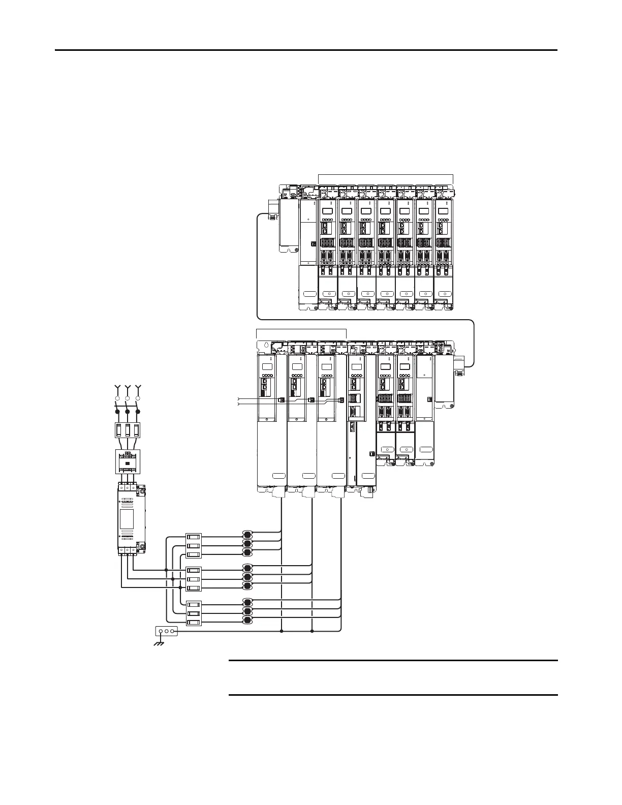
In this example, two drive clusters in the same cabinet are connected by the
same 458…747V DC-bus voltage. Kinetix 5700 capacitor modules provide
connection points for the DC bus. The extension module is needed only when
the DC-bus system current exceeds 104 A, and can support up to 208 A
maximum external DC-bus current.
Figure 206 - Extended DC-bus Installation
MOD
NET
MOD
NET
MOD
NET
MOD
NET
2
1
1
4
I/O
2
1
2
1
2
1
UFB
UFB-A UFB-B
UFB-A UFB-B
D+
D-
D+
D-
D+
D-
MF-A MF-B MF-A MF-B
D+
D-
MBRK
+
-
MOD
NET
2
1
1
4
I/O
MOD
NET
2
1
1
4
I/O
MOD
NET
MOD
NET
2
1
2
1
UFB-A UFB-B
UFB-A UFB-B
D+
D-
D+
D-
MF-A MF-B MF-A MF-B
D+
D-
MOD
NET
2
1
UFB-A UFB-B
D+
D-
MF-A MF-B
D+
D-
MOD
NET
MOD
NET
2
1
2
1
UFB-A UFB-B
UFB-A UFB-B
D+
D-
D+
D-
D+
D-
MF-A MF-B MF-A MF-B
D+
D-
MOD
NET
2
1
UFB-A UFB-B
D+
D-
MF-A MF-B
D+
D-
MOD
NET
2
1
UFB-A UFB-B
D+
D-
MF-A MF-B
D+
D-
MODULE
STATUS
MOD
DC BUS
MOD
DC BUS
MODULE
STATUS
D+
D-
MF
1
I/O-A
6
510
1
I/O-B
6
510
1
I/O-A
6
510
1
I/O-B
6
510
1
I/O-A
6
510
1
I/O-B
6
510
1
I/O-A
6
510
1
I/O-B
6
510
1
I/O-A
6
510
1
I/O-B
6
510
1
I/O-A
6
510
1
I/O-B
6
510
1
I/O-A
6
510
1
I/O-B
6
510
1
I/O-A
6
510
1
I/O-B
6
510
1
I/O-A
6
510
1
I/O-B
6
510
1
I/O
6
5
10
Bonded Cabinet
Ground Bus
DC-bus Extension
Circuit
Protection
DC-bus Extension
1321-3R80-B
Line Reactors
(required components)
2198-P208 DC-bus Power Supplies
Single-axis
Inverter
Dual-axis
Inverters
Extension
Module
Capacitor
Module
Extension
Module
Dual-axis Inverters
Capacitor
Module
Magnetic Contactor
(M1) Control String
Line Disconnect
Device
324…528V AC
Three-phase
Input Power
Magnetic (M1)
Contactor
2198-DBR200-F
AC Line Filter
(required for CE)
Kinetix 5700 Servo Drives
Cluster 1 (front view)
Kinetix 5700 Extended Servo Drives
Cluster 2 (front view)
Shared DC-bus and
24V DC Control Power
Bulletin 2198 Shared-bus
Connection System
(24V shared-bus connection
system is optional)
ATTENTION: Circuit protection can
be added after the power supply
cluster to help protect converters and
inverters from damage in the event of
a DC-bus cable short-circuit.
Circuit
Protection
IMPORTANT When two or three DC-bus power supplies are wired together in the same
drive cluster, they must all be catalog number 2198-P208.
 Loading...


