Rockwell Automation Publication 2198-UM002G-EN-P - February 2019 53
Plan the Kinetix 5700 Drive System Installation Chapter 2
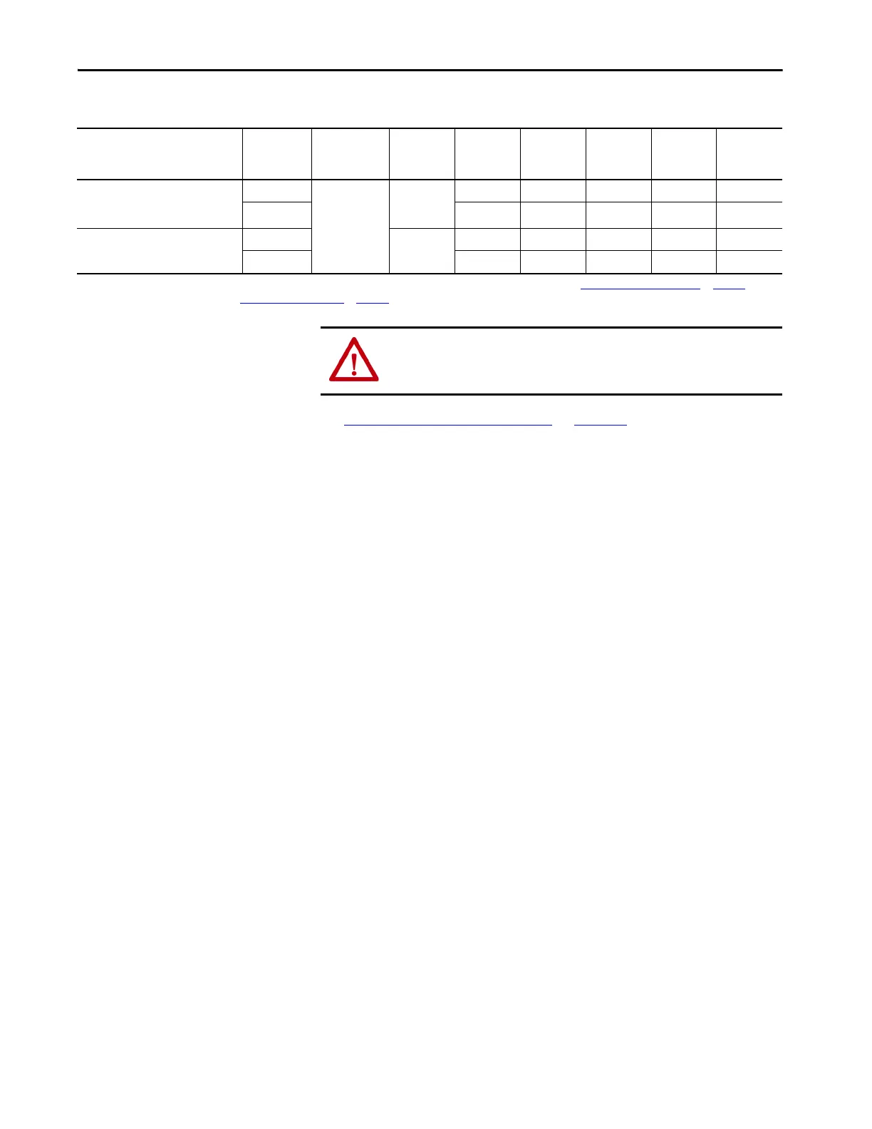
Table 17 - Compatible Active Shunt Specifications (no internal brake resistor)
See External Active-shunt Connections on page 183, when making active
shunt connections.
Kinetix 5700 Power Supply
Powerohm
Resistors
Cat. No.
(1)
Input Voltage,
nom
Turn -on
Bus Voltage
Continuous
Power
kW
Resistance
(internal)
Ω
Resistance
(minimum)
Ω
Continuous
Current
Amps
Peak
Current
Amps
2198-Pxxx DC-bus power supply or
2198-RPxxx regenerative bus supply
when DC-bus regulation is not enabled.
PWB035
480V AC
750V DC
26.25 – 7.5 35 100
PWB110 82.5 – 2.5 110 300
2198-RPxxx regenerative bus supply
when DC-bus regulation is enabled.
PWB035-800
800V DC
26.25 – 8.0 35 100
PWB110-800 82.5 – 2.7 110 300
(1) How the Powerohm PWBxxx shunts connect to the 2198-Pxxx DC-bus power supply and 2198-RPxxx regenerative bus supply is explained in External Active-shunt Connections on page 183 and
illustrated with interconnect diagrams in Active Shunt Wiring Examples
on page 360.
ATTENTION: Do not use Powerohm active-shunt modules at input line
voltages that exceed 528V AC. Active-shunt thermal-overload shutdown can
occur if input line voltage exceeds 528V AC.
 Loading...


