Rockwell Automation Publication 2198-UM002G-EN-P - February 2019 71
Plan the Kinetix 5700 Drive System Installation Chapter 2
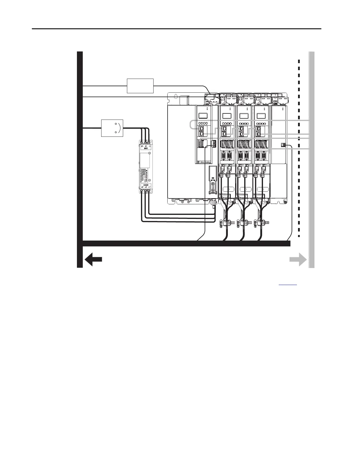
Figure 39 - Noise Zones (regenerative bus supply)
(1) When space to the right of the module does not permit 150 mm (6.0 in.) segregation, use a grounded steel shield instead. For
examples, refer to the System Design for Control of Electrical Noise Reference Manual, publication GMC-RM001
.
(2) When the 2198-H2DCK feedback converter kit or 2198-K57CK-D15M universal feedback kit is used, feedback cable routes in the
clean wireway.
D
C
D
D
VD
C
MOD
NET
2
1
UFB-A UFB-B
D+
D-
MF-A MF-B
D+
D-
MOD
NET
2
1
UFB-A UFB-B
D+
D-
MF-A MF-B
D+
D-
MOD
NET
2
1
UFB-A UFB-B
D+
D-
MF-A MF-B
D+
D-
MOD
DC BUS
C
D
1
I/O-A
6
510
1
I/O-B
6
510
1
I/O-A
6
510
1
I/O-B
6
510
1616
MOD
NET
2
1
1
I/O
6
5
10
OK+
OK–
EN–
EN+
Dirty Wireway
Clean Wireway
Motor Cables
(2)
Circuit
Protection
24V DC
Power Supply
AC Line Filter
(required for CE)
Kinetix 5700 Servo Drive System
(1)
(1)
Very Dirty Filter/AC Input
Connections Segregated
(not in wireway)
Route motor cables
in shielded cable.
Route registration and communication
signals in shielded cables.
Safety Cable
(hardwired drives only)
Module
Status
Contactor Enable
 Loading...


