Rockwell Automation Publication 2094-UM002G-EN-P - August 2016 155
Configure and Start the Kinetix 6200 Drive System Chapter 6
14. From the Bus Regulator Catalog Number pull-down menu, choose the
shunt option appropriate for your actual hardware configuration.
15. Calculate additional bus capacitance, if this applies to your application,
and enter the value here (version 20.00 or later), or refer to Appendix F
on page 307
to set the Add Bus Cap parameter.
The Additional Bus Capacitance field applies only to the IAM power
module.
16. Click OK.
17. Repeat step 1
through step 10 for each Bulletin 2094 AM power module
and control module combination, and each IDM unit.
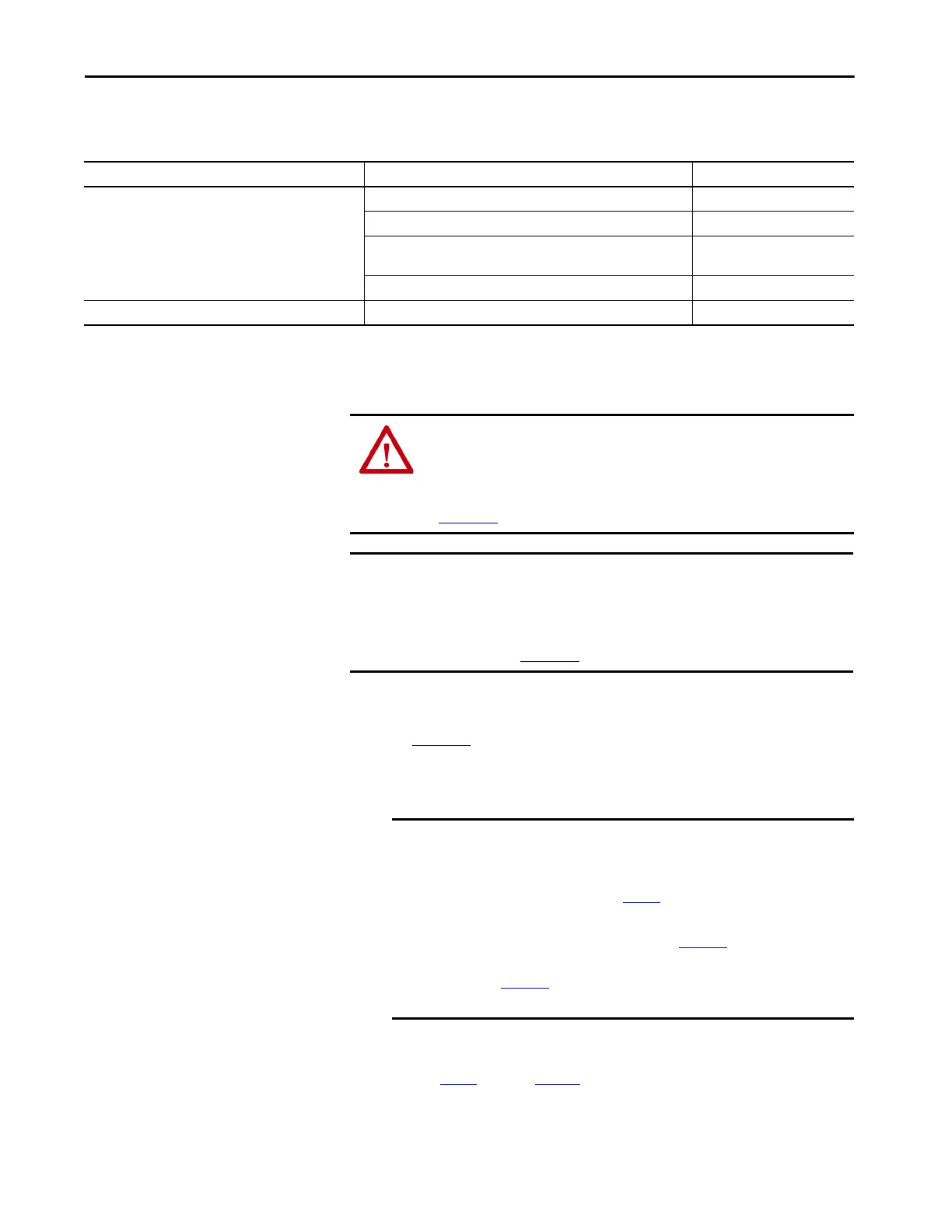
If your IAM power module is And your hardware configuration includes this shunt option Then choose
Configured as an IAM module or
common-bus leader IAM module
(1)
Internal shunt resistors only Internal or <none>
Bulletin 2094 (rail mounted) shunt module
(3)
2094-BSP2
Bulletin 1394 passive shunt module (connected to the 2094-BSP2 shunt
module)
1394-SRxxxx
External active shunt module Internal or <none>
Configured as a common-bus follower IAM module
(2)
N/A. Shunts are disabled on follower IAM module CommonBus Follow
(1) Drive does not accept Internal, <none>, 2094-BSP2, or 1394-SRxxxx selection if DC bus voltage is present without having three-phase power applied.
(2) Drive does not accept CommonBus Follow selection if three-phase power or DC bus power is applied.
(3) To use the 2094-BSP2 shunt module with 2094-BCxx-Mxx-M power modules, you must be using Motion Database 5.12.1 or later. Contact Rockwell Automation Technical Support for more
information.
To avoid damage to your Bulletin 1394 external shunt module when wired to
the 2094-BSP2 shunt module, verify that the proper 460V fuse is installed prior
to applying power.
Refer to Kinetix Motion Accessories Specifications Technical Data, publication
KNX-TD004
, for more information.
IMPORTANT When configured to use the Bulletin 1394 or 2094 shunt modules, the IAM
bus regulator capacity attribute displays the utilization of total shunt power
available (as a percent) based on the power rail configuration.
Refer to Kinetix Motion Accessories Specifications Technical Data,
publication KNX-TD004
, for shunt power specification and examples.
IMPORTANT DC common-bus applications must calculate Total Bus Capacitance
and Additional Bus Capacitance and set the Add Bus Cap parameter
in the leader IAM power module. However, you can set the
parameter as shown in step 15
or by using the Logix Designer
application, as shown in Appendix F.
Refer to Appendix C beginning on page 267
, for more information
on making the calculations. Refer to Appendix F beginning on
page 307
, for more information on setting the Add Bus Cap
parameter.

 Loading...


