Rockwell Automation Publication 2094-UM002G-EN-P - August 2016 71
Connector Data and Feature Descriptions Chapter 4
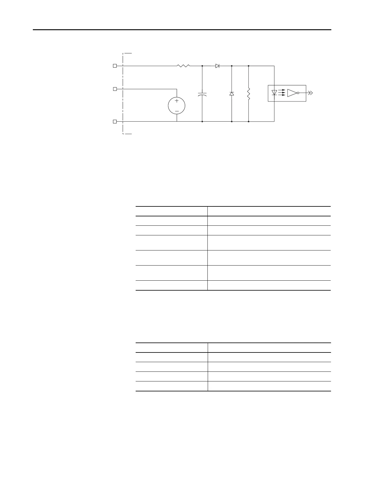
Figure 33 - Digital Input Circuitry
Ethernet Communication Specifications
The PORT1 and PORT2 (RJ-45) Ethernet connectors are provided for
communication with the Logix controller (Kinetix 6500 control modules) and
for programming the safety configuration (Kinetix 6200 and Kinetix 6500
control modules).
Sercos Communication Specifications
The Rx and Tx sercos connectors are provided on the Kinetix 6200 control
module for communication with the Logix5000™ controller.
INPUTx
24VCOM
IOD-39
IOD-41, IOD-42, IOD-43, or IOD-44
IOD-40
Kinetix 6200 or Kinetix 6500 Control Module
24V DC
Attribute Value
Communication 100BASE-TX, full duplex
Cyclic update period 1.0 ms, min
Embedded switch features
Three-port, cut-through, time correction on IEEE-1588 packets, limited
filtering, quality of service with four priority levels
Auto MDI/MDIX crossover detection/
correction
Yes
Port-to-port time synchronization
variation
100 ns, max
Cabling CAT5e shielded, 100 m (328 ft) max
Attribute Value
Data rates 4 and 8 Mbps, selectable via DIP switch
(1)
(1) The Kinetix 6000M IDM system supports only 8 Mbps and is hardwired for this setting.
Light intensity Low power or high power, selectable via DIP switch
Cyclic update period 500 μs, min
Node addresses 001…099
(2)
(2) Node address assignments begin with the IAM module. Node addresses for additional axes on the same power rail are assigned
by incrementing from left to right (starting with the IAM module address).
Each IDM unit has it’s own node address switches and can be set to any valid address. However, node addresses for the IAM and
AM modules on the power rail and for IDM units must be unique.

 Loading...


