120 Rockwell Automation Publication 2099-UM001D-EN-P - December 2012
Chapter 5 Configure and Startup the Kinetix 7000 Drive System
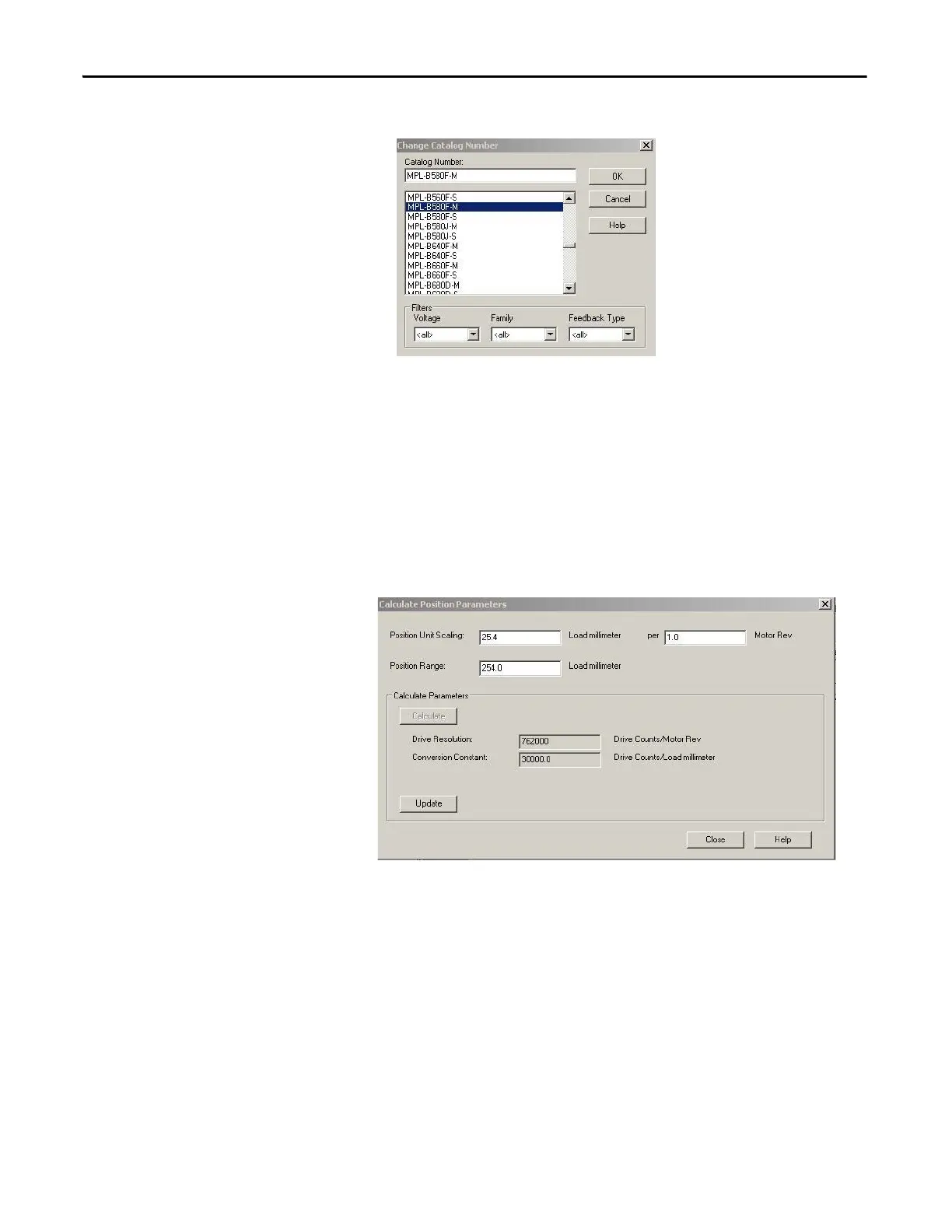
16. The Change Catalog Number dialog box appears.
17. Select the appropriate motor catalog number for your application. It is
important to verify the motor catalog number on the motor nameplate as
well as in your design specification.
18. Click OK.
19. Click Calculate, to configure the drive resolution and conversion constant.
The position unwind is also calculated if rotary load is used.
20. In this example, a linear load is used and a 25.4 mm (1 in.) movement on a
ballscrew is made with every 1 motor revolution. The total position
movement on the ballscrew is 254 mm (9.8 in.).
21. Click Update.
22. Click Close.
23. The Drive Enable Input Checking is selected by default. When checked
(default) a hard drive enable input signal on the IOD connector (pin 2) is
required. Uncheck Drive Enable Input Checking if a hard drive enable
input signal is not required.
 Loading...


