Rockwell Automation Publication 2080-UM004D-EN-E - March 2018 15
Install and Wire Your Module Chapter 2
Wiring Considerations and
Applications for 2080-RTD2
Two-wire and Three-Wire Wiring
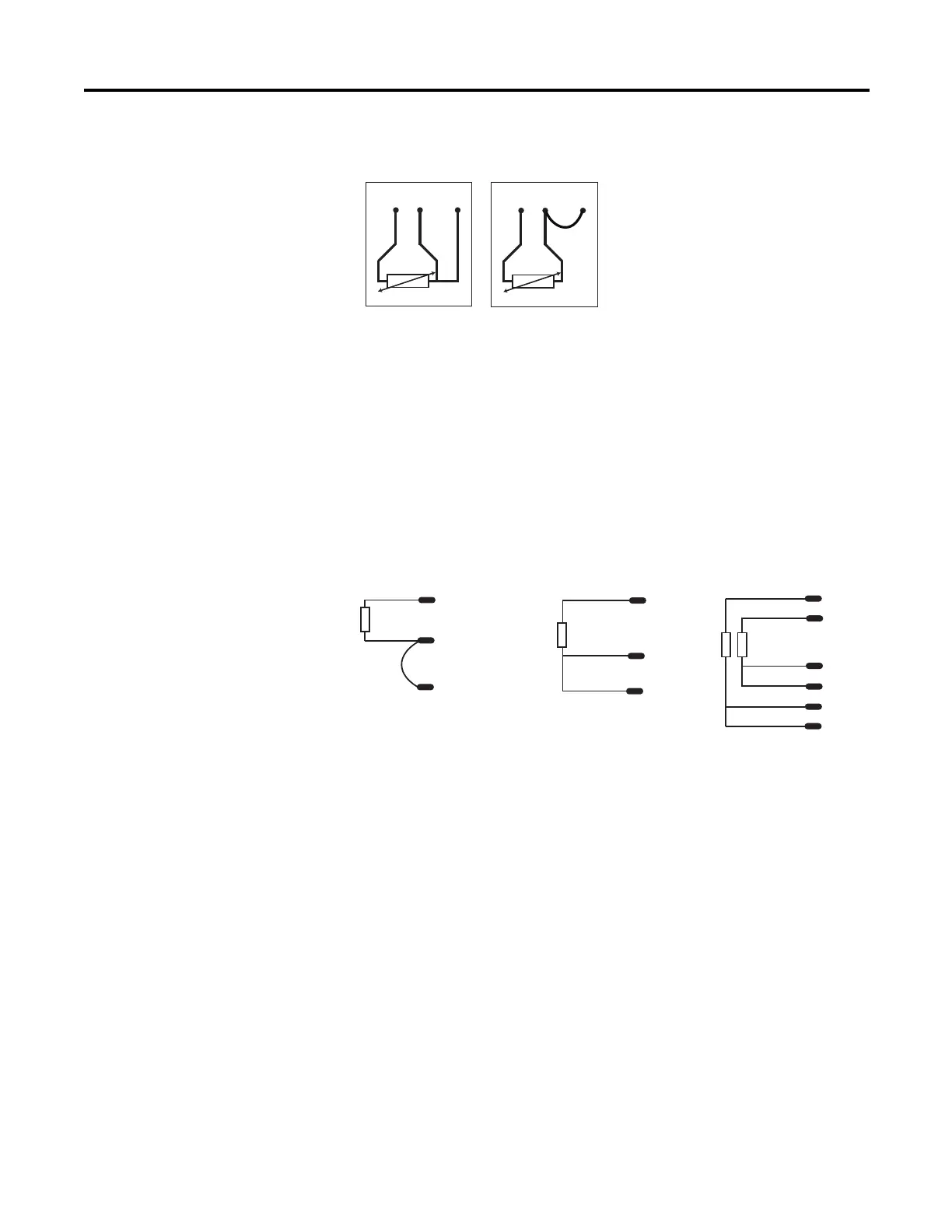
Wire the RTD Sensors
In an RTD sensor, the sensing element is always connected between two wires of
different colors. Wires of the same color are shorted and form the compensation
leads. Measuring resistance between these wires confirms the position of sensing
element and compensation elements. Compensation elements will always show
0ohms.
Wire the Sensors
For better accuracy in noisy industrial environments, 3- or 4-wire RTD sensors
are mostly used. While using these sensors, the resistance added by lead lengths is
compensated by an additional third wire in case of 3-wire RTD and two
additional wires, in bridge configuration, in case of 4-wire RTD. For 2-wire RTD
sensor in this module, this lead compensation is provided by using an external
50 mm 22 AWG shorting wire between terminals A2, A3 and B2, B3 for channel
0 and 1, respectively. Shielded twisted pair cables are to be utilized for remote use
of these sensors with cable shield grounded at controller end.
1 23
12 3
white
red
Ch0+
Ch0-
Ch0L
white
red
red
green
black
black
white
red
red
Ch1+
Ch1-
Ch1L
Ch0-
Ch0L
Ch0+
Ch0-
Ch0L
Ch0+
2-wire sensor
connection
3-wire single
sensor connection
3-wire dual
sensor connection
45778
NOTE: This illustration provides for channel 0 only for 2- and 3-
wire single sensor connections. The wire colors illustrate a
particular type of RTD sensor available in market.
 Loading...


