16 Rockwell Automation Publication 2080-UM004D-EN-E - March 2018
Chapter 2 Install and Wire Your Module
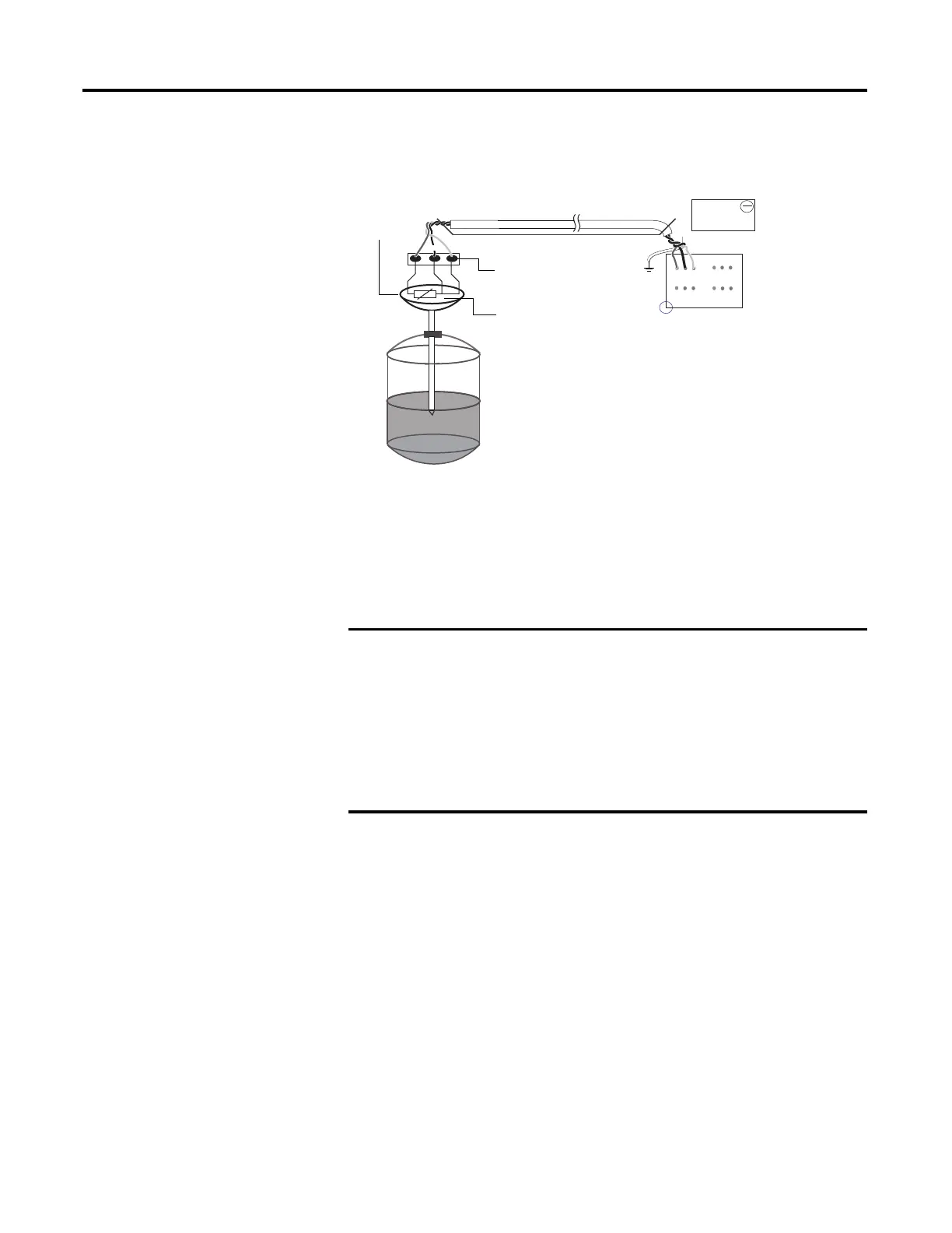
Wire the RTD Module and RTD Sensor in the Field
The RTD sensing element should always be connected between terminals B1(+)
and B2(-) for channel 1, and A1(+) and A2(-) for channel 0 in the module.
Terminals B3 and A3 should always be shorted to B2 and A2, respectively, to
complete the constant current loop. Mismatch in wiring can cause erroneous,
over, or underrange readings.
Cabling used with the 2080-TC2/RTD2 modules have to be shielded
twisted cores with the shield wire shorted to chassis ground at controller
end. It is advisable to use 22 AWG wires to connect the sensors to the
module. Use sensors dipped in oil-filled thermowells for stable and
uniform readings. Recommended cable type: Alpha wire P/N 5471C.
Performance is dependent on the application. For better noise immunity,
cable length should ideally be less than 3 m because the plug-ins are
non-isolated. For longer cable length requirements, use the 2085
expansion I/O modules instead.
1
2
3
1 2 3 4 5 6
1 2 3 4 5 6
2080-RTD2
B
A
Red
Green
Black
Blue
Red
Blue
Black
Process
temperature
Measurement
Shielded twisted wire cable
Field screw
junction box
3-wire
RTD
Oil filled
thermowell
45779
3-wire RTD shown
Cable tray/conduit
 Loading...


