Rockwell Automation Publication 2080-UM004D-EN-E - March 2018 27
High Speed Counter – 2080-MOT-HSC Chapter 4
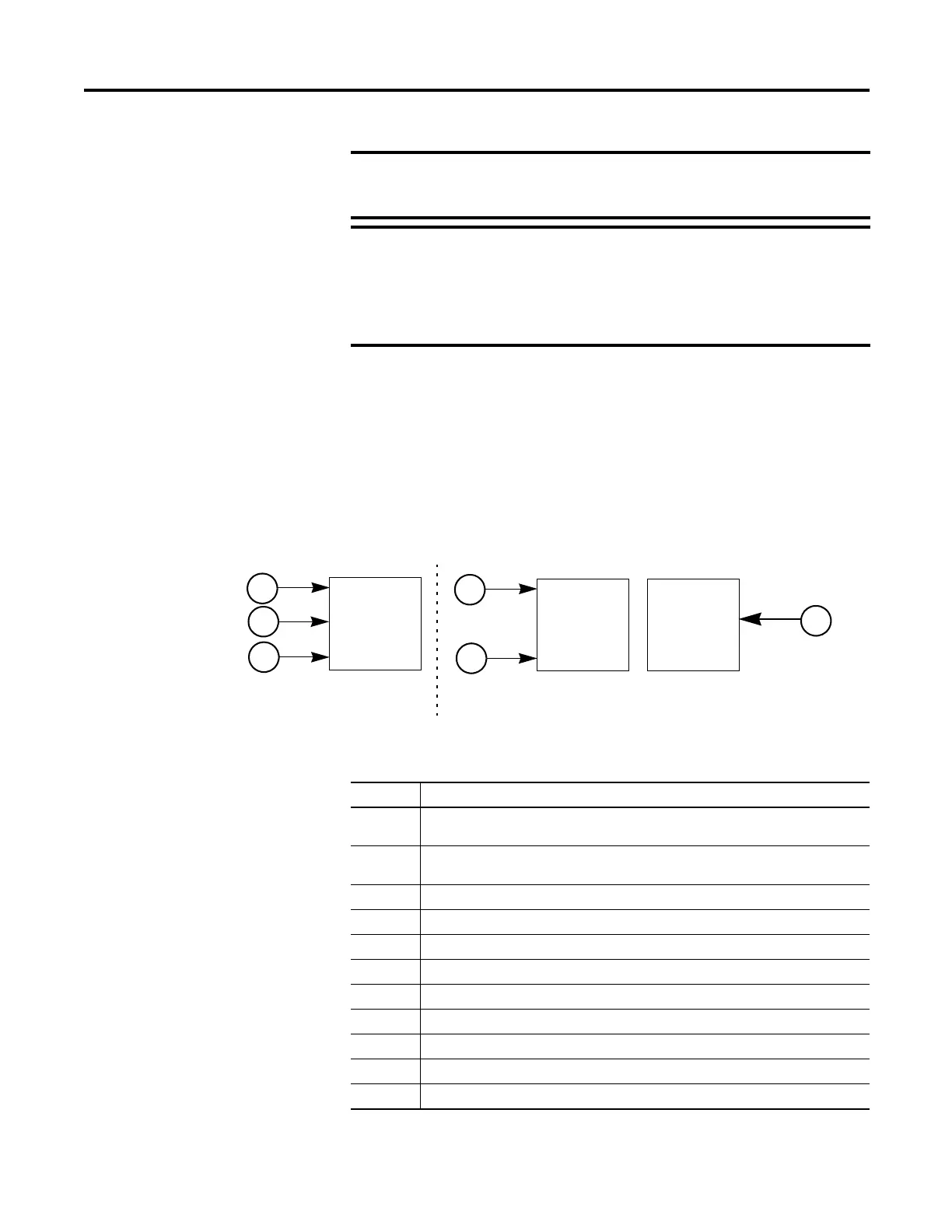
Number of Counters: 1 to 2
The module may be configured, using HSC_Mode, to use the inputs as 1 or 2
counters.
1 counter: A, B, Z = Counter 0
2 counters: A, Z = Counter0; B = Counter 1
Counter Pin Usage
For low frequency pulses, filter times should be set appropriately to
avoid extra pulses from a noisy environment. For high frequency
pulses, shielded cable must always be used.
When the controller is power cycled, the value of the counters are
reset to zero.
The counters are not reset to zero for program download. For
example, if using the feedback axis, use the MC_SetPosition function
block to reset the position to zero.
A
B
Z
Counter
HSC_Mode = 2 to 11
A
Z
Counter
HSC_Mode = 0, 1, 12, and 13
Counter
B
Input Operational Modes
Mode Description
0 Up Counter – The accumulator is immediately cleared (0) when it reaches the high
preset. A low preset cannot be defined in this mode.
1 Up Counter with external reset and hold – The accumulator is immediately cleared (0)
when it reaches the high preset. A low preset cannot be defined in this mode.
2 Counter with external direction.
3 Counter with external direction, reset, and hold.
4 Two input counter (up and down).
5 Two input counter (up and down) with external reset and hold.
6 Quadrature counter (phased inputs A and B).
7 Quadrature counter (phased inputs A and B) with external reset and hold.
8 Quadrature X4 counter (phased inputs A and B).
9 Quadrature X4 counter (phased inputs A and B) with external reset and hold.
10 Quadrature X2 counter (phased inputs A and B).
 Loading...


