1 Publication 1764-UM001B-EN-P - April 2002
Chapter
6
Using Real-Time Clock and Memory Modules
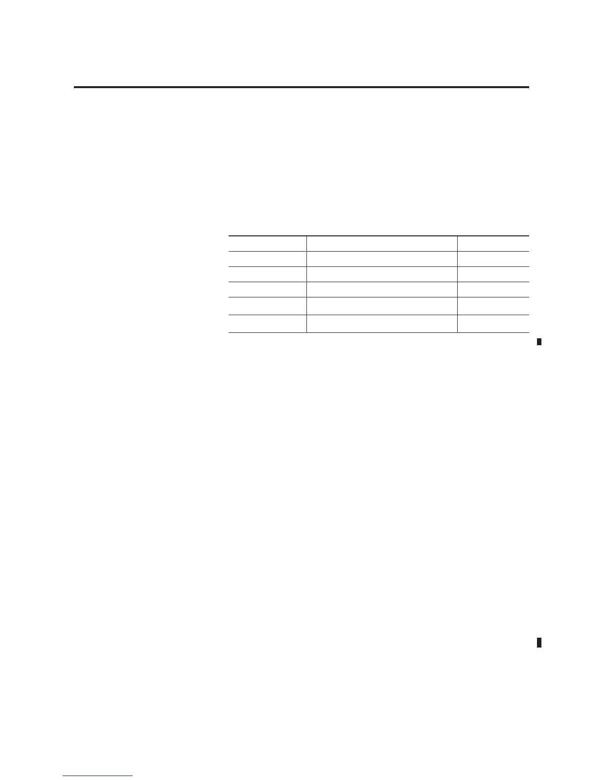
Five modules with different levels of functionality are available for use
with the MicroLogix 1500 controller.
Real-Time Clock Operation
Removal/Insertion Under Power
The real-time clock module can be installed or removed at any time
without risk of damage to either the module or the controller. If a
module is installed while the MicroLogix 1500 is in an executing mode
(Run or Remote Run), the module is not recognized until either a
power cycle occurs, or until the controller is placed in a
non-executing mode (program mode or fault condition).
Removal of the memory module is detected within one program scan.
Removal of the real-time clock under power causes the controller to
write zeros to the (RTC) Function File.
Real-Time Clock Function File
The real-time clock provides year, month, day of month, day of week,
hour, minute, and second information to the Real-Time Clock (RTC)
Function File in the controller. Refer to the MicroLogix 1200 and
MicroLogix 1500 Instruction Set Reference Manual, publication
1762-RM001 for information about the RTC function file.
Catalog Number Function Memory Size
1764-RTC Real-Time Clock not applicable
1764-MM1 Memory Module 8K
1764-MM1RTC Memory Module and Real-Time Clock 8K
1764-MM2
(1)
(1) For 1764-LRP programs greater than 8k, use the 1764-MM2 or 1764-MM2RTC.
Memory Module 16K
1764-MM2RTC
(1)
Memory Module and Real-Time Clock 16K

 Loading...


