Publication 1764-UM001B-EN-P - April 2002
Installing Your Controller 2-13
Mounting the Controller
ATTENTION
!
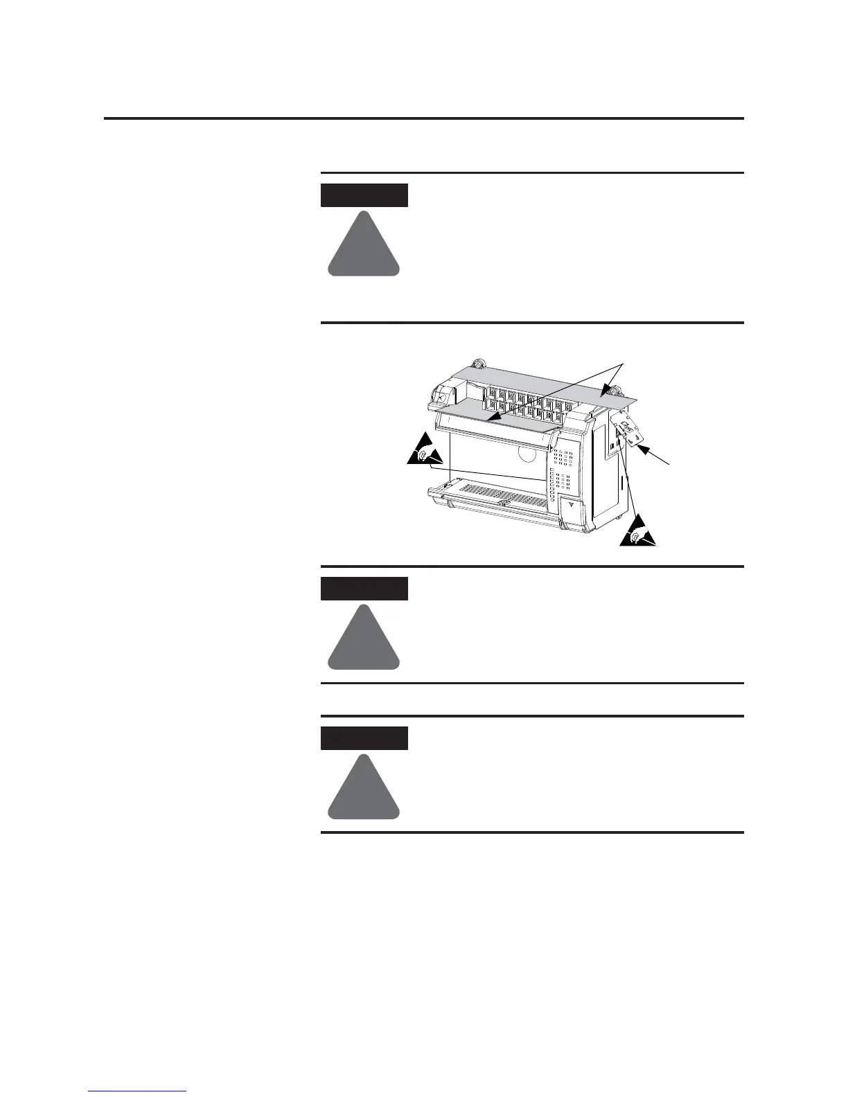
Do not remove protective debris strips until after the
base and all other equipment in the panel near the
base is mounted and wiring is complete. The debris
strips are there to prevent drill fragments, wire
strands and other dirt from getting into the controller.
Once wiring is complete, remove protective debris
strips and install processor unit. Failure to remove
strips before operating can cause overheating.
ATTENTION
!
Be careful of metal chips when drilling mounting
holes for your controller or other equipment within
the enclosure or panel. Drilled fragments that fall
into the controller could cause damage. Do not drill
holes above a mounted controller if the protective
debris strips have been removed.
ATTENTION
!
Electrostatic discharge can damage semiconductor
devices inside the base unit. Do not touch the
connector pins or other sensitive areas.
Protective
Debris Strips
ESD Barrier

 Loading...


