Publication 1764-UM001B-EN-P - April 2002
2-12 Installing Your Controller
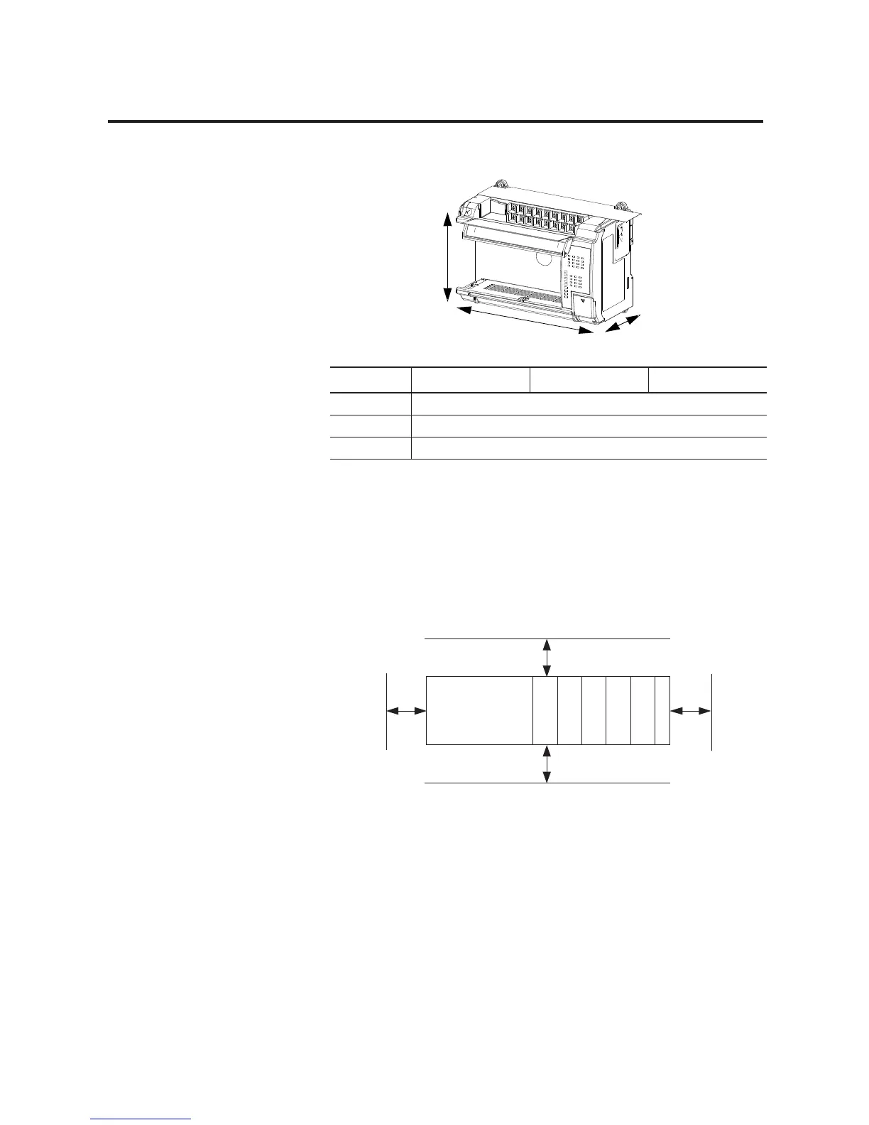
Base Unit Mounting
Dimensions
Controller Spacing
The base unit is designed to be mounted horizontally, with the
Compact™ expansion I/O extending to the right of the base unit.
Allow 50 mm (2 in.) minimum of space on all sides for adequate
ventilation, as shown below.
Dimension
(1)
(1) See Controller Dimensions on page A-9 for more dimensional information.
1764-24AWA 1764-24BWA 1764-28BXB
Height (A) DIN latch open: 138 mm (5.43 in.), DIN latch closed: 118 mm (4.65 in.)
Width (B) 168 mm (6.62 in.)
Depth (C) 87 mm (3.43 in.)
A
C
B
Controller
Top
Side
Bottom
Side
Compact I/O
Compact I/O
Compact I/O
Compact I/O
Compact I/O
End Cap

 Loading...


