Publication 1764-UM001B-EN-P - April 2002
4-10 Communication Connections
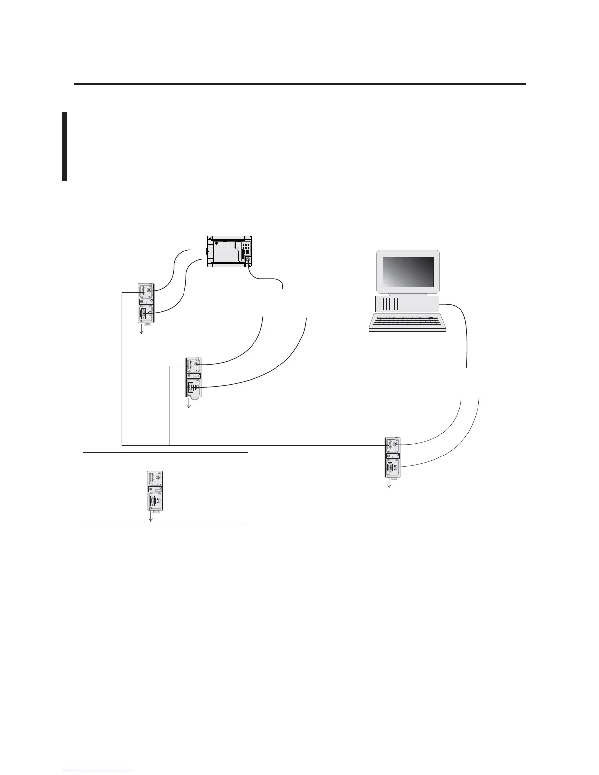
Connecting to a DH-485
Network
The following network diagrams provide examples of how to connect
MicroLogix 1500 controllers to the DH-485 network using the
Advanced Interface Converter (AIC+, catalog number 1761-NET-AIC).
For more information on the AIC+, see the Advanced Interface
Converter and DeviceNet Interface Installation Instructions,
Publication 1761-5.11.
DH-485 Network with a MicroLogix 1500 Controller
TERM
A
B
COM
SHLD
CHS GND
TX
TX PWR
TX
DC SOURCE
CABLE
EXTERNAL
TERM
A
B
COM
SHLD
CHS GND
TX
TX PWR
EXTERNAL
TERM
A
B
COM
SHLD
CHS GND
TX
TX PWR
EXTERNAL
TERM
A
B
COM
SHLD
CHS GND
TX
TX PWR
EXTERNAL
MicroLogix 1500
connection from port 1 or port 2
to MicroLogix Channel 0
1761-CBL-AM00
or 1761-CBL-HM02
1761-CBL-AP00
or 1761-CBL-PM02
1761-CBL-AP00
or 1761-CBL-PM02
1747-CP3
or 1761-CBL-AC00
24V dc
(user supply needed if not
connected to a controller)
AIC+
24V dc
(user supplied)
Personal Computer
PC to port 1
or port 2
AIC+
AIC+
connection from port 1 or port 2
to MicroLogix Channel 1
1747-CP3
or 1761-CBL-AC00
1761-CBL-AP00
or 1761-CBL-PM02
24V dc
(user supply
needed if not
connected to
a controller)
REFERENCE: AIC+ Port Identification
Port 2: mini-DIN 8 RS-232
Port 3: RS-485
Port 1: DB-9 RS-232

 Loading...


