Publication 1764-UM001B-EN-P - April 2002
2-10 Installing Your Controller
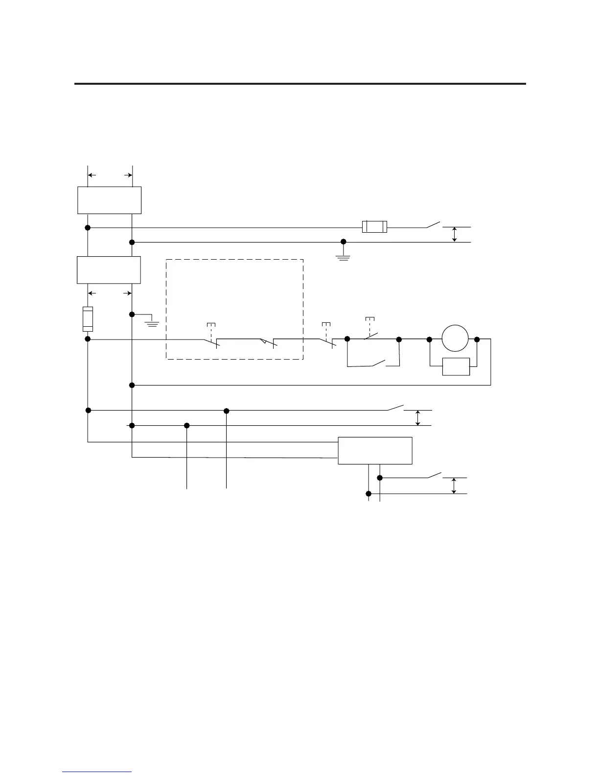
Schematic (Using IEC Symbols)
Disconnect
Isolation
Transformer
Emergency-Stop
Push Button
Fuse
MCR
230V ac
I/O
Circuits
Operation of either ofthese contacts will
remove power from the external I/O
circuits, stopping machine motion.
Fuse
Overtravel
Limit Switch
MCR
MCR
MCR
Stop
Start
Line Terminals:
Connect to terminals of Power Supply
(1764-24AWA and 1764-24BWA).
115V ac or
230V ac
I/O Circuits
L2
230V ac
Master Control Relay (MCR)
Cat. No. 700-PK400A1
Suppressor
Cat. No.
700-N24
MCR
Suppr.
24V dc
I/O
Circuits
(Lo) (Hi)
dc Power Supply.
Use IEC 950/EN 60950
X1
X2
115V ac
or 230V ac
Line Terminals: Connect to 24V dc
terminals of Power Supply.
_
+

 Loading...


