Publication 1764-UM001B-EN-P - April 2002
F-6 System Loading and Heat Dissipation
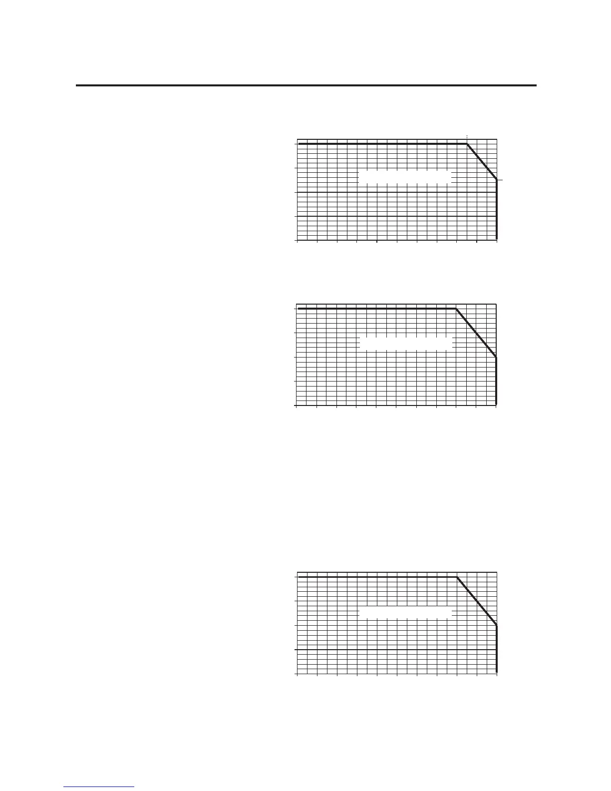
Figure F.2 1769-PA2 Current with +24V dc User Load = 0.2A
Figure F.3 1769-PA2 Current with +24V dc User Load = 0.25A
System Using a 1769-PB2
To validate your system, the total 5V dc current and 24V dc current
consumed must be considered. The I/O modules must be distributed,
such that the current consumed from the left or right side of the
power supply never exceeds 2A at 5V dc and 1.0A at 24V dc. Use the
current graph below to determine if the power supply loading in your
system is within the allowable range.
Figure F.4 1769-PB2 Current
0.0 0.1 0.2 0.3 0.4 0.5 0.6 0.7 0.8 0.9 1.0
0.0
0.5
1.0
1.5
2.0
+5V dc Load (Amps)
+24V dc Load (Amps)
Valid Operating Range
0.0 0.1 0.2 0.3 0.4 0.5 0.6 0.7 0.8 0.9 1.0
0.0
0.5
1.0
1.5
2.0
+5V dc Load (Amps)
+24V dc Load (Amps)
Valid Operating Range
0.0 0.1 0.2 0.3 0.4 0.5 0.6 0.7 0.8 0.9 1.0
0.0
0.5
1.0
1.5
2.0
+5V dc Load (Amps)
+24V dc Load (Amps)
Valid Operating Range

 Loading...


