EasyManuals Logo

Allen-Bradley micrologix 1500 User Manual

Allen-Bradley micrologix 1500
174 pages
To Next Page IconTo Next Page
To Previous Page IconTo Previous Page
Page #24 background imageLoading...
Page #24 background image
Publication 1764-UM001B-EN-P - April 2002
1-10 Hardware Overview
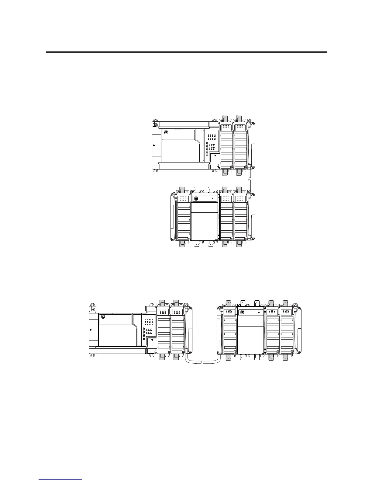
The following illustrations show a MicroLogix 1500 with an expansion
I/O bank.
Vertical Orientation
Horizontal Orientation
Expansion
I/O Bank 1
Expansion
I/O Bank 2
1769-CRRx
(1)
Expansion Cable
1769-ECL
End Cap
(1) The x in this catalog number can be either a 1 or a 3 representing the length of the cable:
1 = 1 foot (305 mm) and 3 = 3.28 feet (1 meter).
Expansion
I/O Bank 1
Expansion
I/O Bank 2
1769-CRLx
(1)
Expansion Cable
1769-ECR
End Cap
(1) The x in this catalog number can be either a 1 or a 3 representing the length of the cable:
1 = 1 foot (305 mm) and 3 = 3.28 feet (1 meter).

Table of Contents

Other manuals for Allen-Bradley micrologix 1500

Questions and Answers:

Question and Answer IconNeed help?

Do you have a question about the Allen-Bradley micrologix 1500 and is the answer not in the manual?

Allen-Bradley micrologix 1500 Specifications

General IconGeneral
Processor Type16-bit
Programming LanguageLadder Logic
MountingDIN rail or panel mount
Programming SoftwareRSLogix 500
Communication PortsRS-232
Power Supply24V DC
Operating Temperature0°C to 55°C (32°F to 131°F)
Controller TypeProgrammable Logic Controller (PLC)

Related product manuals