Publication 1764-UM001B-EN-P - April 2002
Communication Connections 4-21
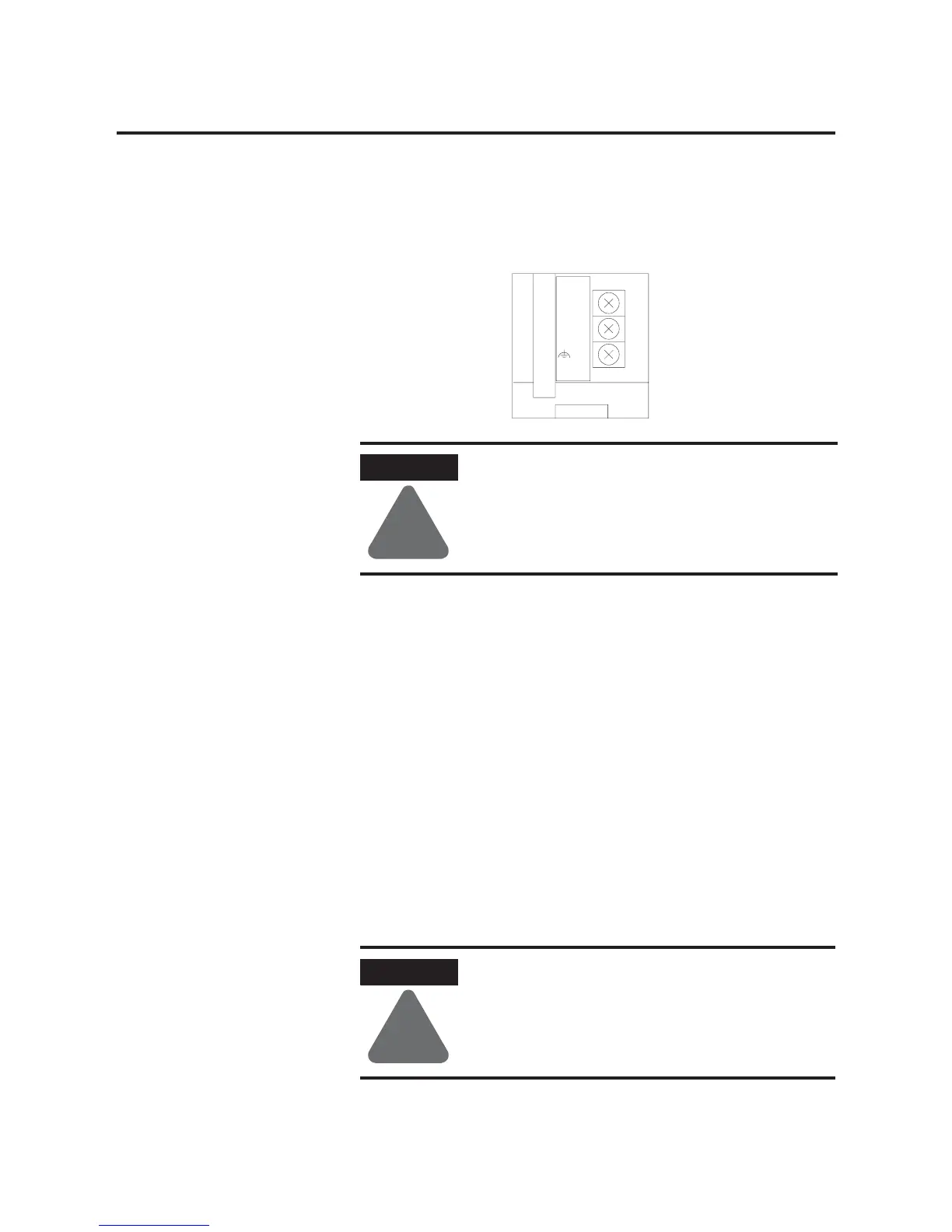
Set the DC Power Source selector switch to EXTERNAL before
connecting the power supply to the AIC+. The following illustration
shows where to connect external power for the AIC+.
Power Options
Below are two options for powering the AIC+:
• Use the 24V dc user power supply built into the MicroLogix
1500 controller. The AIC+ is powered through a hard-wired
connection using a communication cable (1761-CBL-HM02, or
equivalent) connected to port 2.
• Use an external DC power supply with the following
specifications:
– operating voltage: 24V dc +20% or -15%
– output current: 150 mA minimum
– rated NEC Class 2
Make a hard-wired connection from the external supply to the
screw terminals on the bottom of the AIC+.
ATTENTION
!
Always connect the CHS GND (chassis ground)
terminal to the nearest earth ground. This connection
must be made whether or not an external 24V dc
supply is used.
ATTENTION
!
If you use an external power supply, it must be 24V
dc. Permanent damage results if miswired with the
wrong power source.
24VDC
DC
NEUT
CHS
GND
Bottom View

 Loading...


