Publication 1734-UM014A-EN-P - November 2010
56 Configure the Adapter for Direct Connection and Rack Optimization in RSLogix 5000 Software
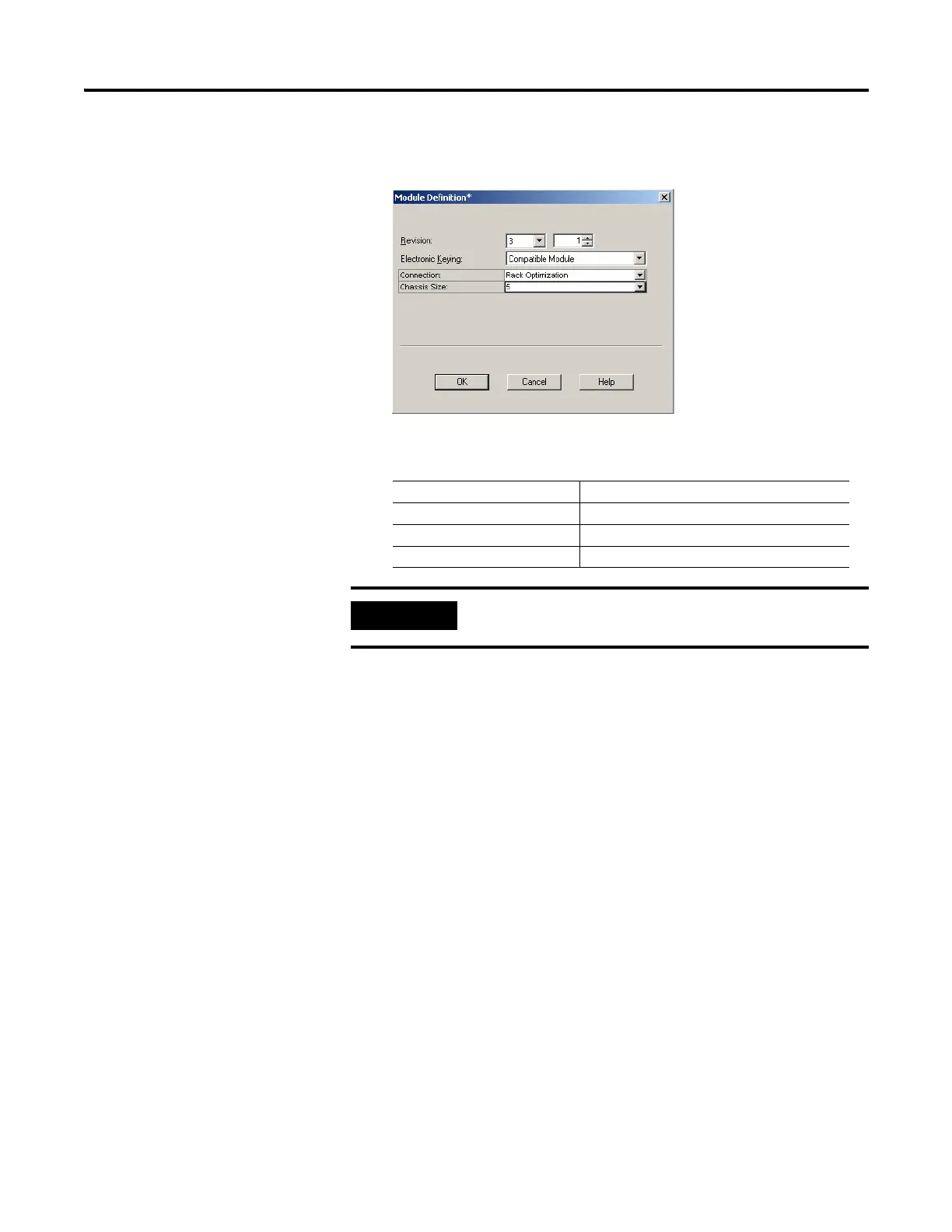
5. On the General tab, click Change...
The Module Definition dialog opens.
6. Enter values for Connection, Chassis Size, Electronic Keying, and
Revision.
Connection choices include:
• None – the adapter makes a direct connection to each of the modules
referenced by the data.
• Rack optimization– digital I/O data is collected into a rack image. This
does not include analog or specialty I/O modules.
• Listen only - rack optimization– read or verify data only, but does not
control the modules. When you have multiple controllers - one
controller is used to control and the other controllers are used to
monitor.
7. Choose Rack Optimization from the Connection drop-down list,
because we are making a mixed connection that includes both a direct
connection and rack-optimized connection.
8. Click OK.
Connection Rack Optimization
Chassis Size 5
Electronic Keying Compatible Module
Revision 3
The chassis size equals 1 for the adapter plus the number of I/O
modules installed (physically present on the I/O backplane).

 Loading...


