Rockwell Automation Publication 22C-IN002E-EN-P - November 2010
Chapter 5
Electrical Installation
Chapter Objectives
This chapter provides information on electrical installation of a PowerFlex
Drive Package for Fan and Pump Applications.
Power Wire Size
Requirements
Wire size should be determined based on the size of the conduit openings,
and applicable local, national and international codes such as NEC/CEC.
Power Terminal Block
Specification
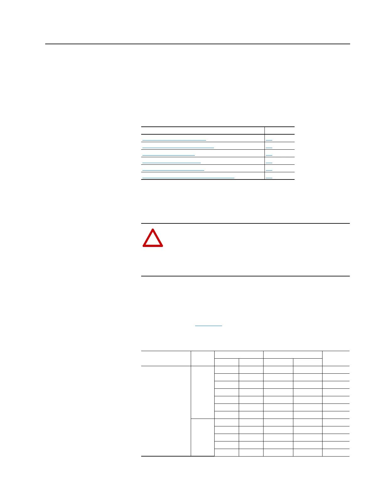
Input power wiring should be sized according to applicable codes to handle
the drive's continuous-rated input current. Output wiring should be sized
according to applicable codes to the handle the drive's continuous-rated
output current. See Table 5.A
for the range of power wire sizes that the
terminals can accommodate.
Table 5.A Power Wire Sizes
For information on . . See page
Power Wire Size Requirements
5-1
Power Terminal Block Specification 5-1
Control and Signal Wiring 5-2
Installing Input Power Wiring 5-2
Installing Output Power Wiring 5-3
Installing an Optional Transformer or Reactor 5-3
ATTENTION: National codes and standards (NEC, VDE, BSI,
etc.) and local codes outline provisions for safely installing
electrical equipment. Installation must comply with specifications
regarding wire types, conductor sizes, branch circuit protection,
and disconnect devices. Failure to do so may result in personal
injury and/or equipment damage.
Name Package
Hp Wire Size Range
Torque208V AC 480V AC Minimum Maximum
Input Power
L1(R), L2 (S), L3 (T)
A, B 3…5 1…10 14 AWG 8 AWG 12
7.5…10 15…25 14 AWG 4 AWG 35
15…20 30…50 14 AWG 2 AWG 35
25…40 60…100 6 AWG 250 MCM 275
50 125…200 (2) 1/0 350 MCM 275
– 250…300 (2) 2/0 350 MCM 275
– 350 (3) 3/0 350 MCM 275
C – 3…7.5 22 AWG 8 AWG 13
– 10…30 14 AWG 4 AWG 19
– 40 12 AWG 1/0 AWG 40
– 50…60 12 AWG 2 AWG 90
– 75…100 6 AWG 250 MCM 275

 Loading...


