2-10 3 Contactor Full Feature Bypass with Disconnect Package (Style B/N)
Rockwell Automation Publication 22C-IN002E-EN-P - November 2010
Bypass Running
The “Bypass Running” contact is normally open. When the Bypass
Contactor (BC) is closed the Bypass Running” contact will also be closed.
Operating Modes
Selector Switch 1 (SS1) and Selector Switch 2 (SS2), located on the Bypass
Control Panel (CP1), are used to determine the operating state of the 3
Contactor Full Feature Bypass with Disconnect Package. SS1 is used to
select motor control:
• DRIVE = Drive keypad/terminal block controls the motor
• DRIVE TEST = Drive is powered but is not controlling the motor
• BYPASS = Motor runs across 3-Phase line
Jumper P2 on the Bypass Control Panel (CP1) allows the drive to be
powered while running in bypass. This is accomplished by moving Jumper
P2 to position B-C and turning SS1 from BYPASS to DRIVE TEST. If
Jumper P2 is in position A-B, the drive cannot be powered while running in
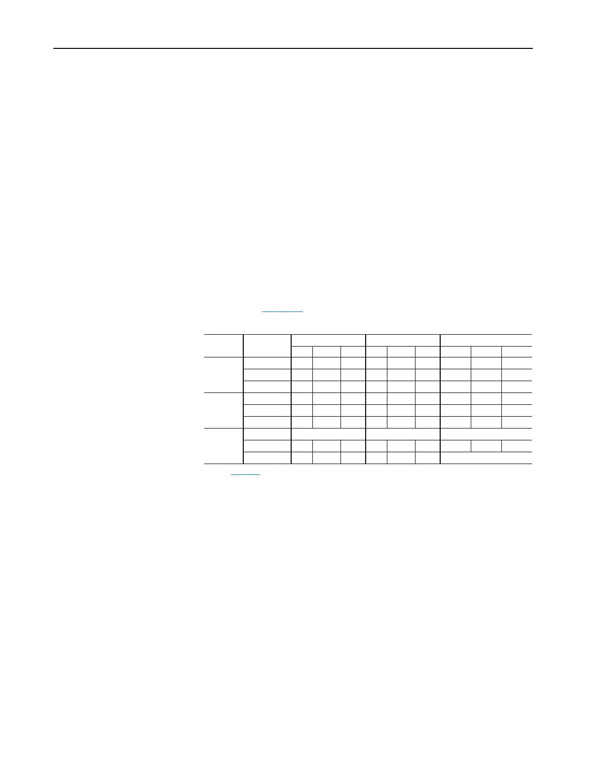
bypass. SS2 selects the source of the Start, Stop, and Drive Speed Reference
as defined in Table 2.F
.
Table 2.F Command and Reference Selection
SS1
(1)
Selection
(1)
See Figure 2.2 for details on selector switch location.
SS2
(1)
Selection
Start Command
(2)
(2)
When “Auto” is selected, the Start Command is defined by P036 [Start Source]. Factory default is configured
for terminal block control. Refer to the PowerFlex 400 User Manual for other control schemes.
Stop Command Drive Speed Reference
(3)
(3)
When “Auto” is selected, the Speed Reference is defined by P038 [Speed Reference]. Analog In1 has control
by factory default. Refer to the PowerFlex 400 User Manual for other control schemes.
TB Keypad None TB Keypad None TB Keypad None
DRIVE
HAND •• •
MOTOR OFF •• •
AUTO ••••
DRIVE
TEST
HAND •• •
MOTOR OFF •• •
AUTO ••••
BYPASS
HAND
Automatically Starts Automatically Starts Motor Runs at Base Speed
MOTOR OFF •• •
AUTO ••
Motor Runs at Base Speed

 Loading...


