2-6 3 Contactor Full Feature Bypass with Disconnect Package (Style B/N)
Rockwell Automation Publication 22C-IN002E-EN-P - November 2010
Electrical Installation
Input Power Wiring
Use 75 °C rated copper conductors only for customer power wiring.
Refer to the PowerFlex 400 User Manual for additional detailed information
about input power wiring recommendations and selection.
To connect AC input power to the drive package:
❏ 1. Select the proper wire size according to NEC and all applicable local
codes and standards. Note that you must punch openings in the Option
Cabinet of the desired conduit size, following NEC and all applicable
local codes and standards. Power terminal block specifications are listed
in Table 2.C
.
❏ 2. Connect the three-phase AC input power leads (three-wire VAC) to the
appropriate terminals. Connect the AC input power leads to terminals
L1, L2, L3 on the fused disconnect switch.
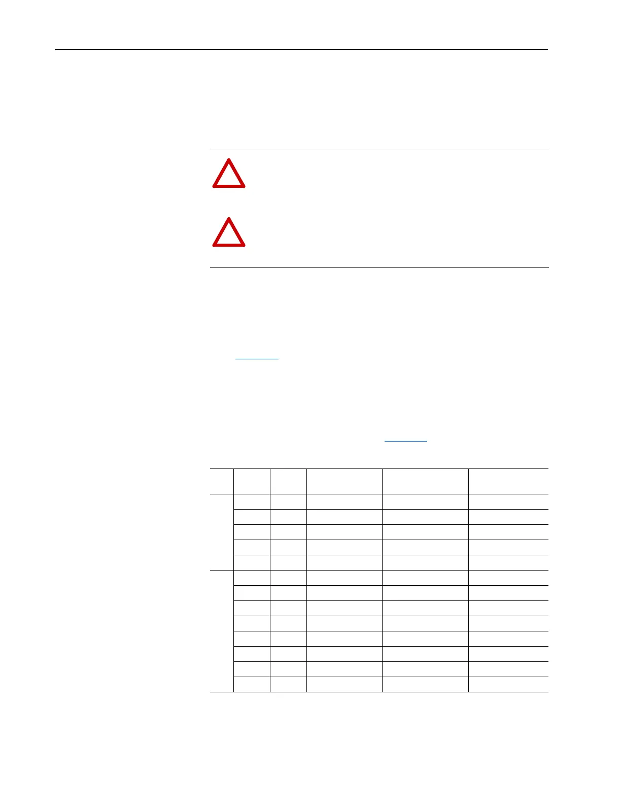
❏ 3. Tighten the AC input terminal power terminals to the proper torque
according to drive type as shown in Table 2.C
.
Table 2.C AC Input Power Terminal Block Specification
ATTENTION: Protect the contents of the options cabinet from
metal chips and other debris while drilling the conduit openings.
Failure to observe this precaution could result in damage to, or
destruction of, the equipment.
ATTENTION: Do not route signal and control wiring with
power wiring in the same conduit. This can cause interference
with drive operation. Failure to observe this precaution could
result in damage to, or destruction of, the equipment.
Volts
AC kW Hp
Maximum Wire
Size
(1)
(1)
Maximum/minimum sizes that the terminal block will accept - these are not recommendations. If national or
local codes require sizes outside the range, lugs may be used.
Minimum Wire Size
Recommended
Torque
208V 2.2…3.7 3.0…5.0 8.4 mm
2
(8 AWG) 2.5 mm
2
(14 AWG) 4.0 N•m (35 lb•in)
5.5…7.5 7.5…10 16.0 mm
2
(4 AWG) 2.5 mm
2
(14 AWG) 4.0 N•m (35 lb•in)
11…15 15…20 33.6 mm
2
(2 AWG) 2.5 mm
2
(14 AWG) 17.5 N•m (155 lb•in)
18.5…30 25…40 250 MCM 10.0 mm
2
(6 AWG) 31.1 N•m (275 lb•in)
37 50 350 MCM 35.0 mm
2
(1/0 AWG) 31.1 N•m (275 lb•in)
460V 2.2…7.5 3.0…10 8.4 mm
2
(8 AWG) 2.5 mm
2
(14 AWG) 4.0 N•m (35 lb•in)
11…18.5 15…25 16.0 mm
2
(4 AWG) 2.5 mm
2
(14 AWG) 4.0 N•m (35 lb•in)
22…37 30…50 33.6 mm
2
(2 AWG) 2.5 mm
2
(14 AWG) 17.5 N•m (155 lb•in)
45…75 60…100 250 MCM 10.0 mm
2
(6 AWG) 31.1 N•m (275 lb•in)
90…110 125…150 (2) 350 MCM (2) 10.0 mm
2
(6 AWG) 31.1 N•m (275 lb•in)
132 200 (2) 350 MCM (2) 35.0 mm
2
(1/0 AWG) 31.1 N•m (275 lb•in)
160…200 250…300 (2) 350 MCM (2) 70.0 mm
2
(3/0 AWG) 31.1 N•m (275 lb•in)
250 350 (2) 400 MCM (2) 70.0 mm
2
(3/0 AWG) 31.1 N•m (275 lb•in)

 Loading...


