3 Contactor Full Feature Bypass with Disconnect Package (Style B/N) 2-5
Rockwell Automation Publication 22C-IN002E-EN-P - November 2010
Control Transformer (T1)
115V AC control power is obtained via a supplied control power
transformer. The control transformer is fused on the primary.
Bypass Control Interface (CP1)
The operator interface on the bypass option box shows the following LEDs:
• Ready (green) - On when power is applied to the drive-bypass unit.
• Interlock Open (amber) - On when the customer interlock or Aux Fault is
de-energized.
• Bypass Run (green) - On when the bypass contactor (BC) is energized.
• Bypass Trip (red) - On when a bypass fault condition exists (for
example, bypass motor overload has tripped).
• Purge (amber) - On when the purge condition is active.
• Drive Output Enable (Green) - On when the drive output contactor
(DOC) is energized.
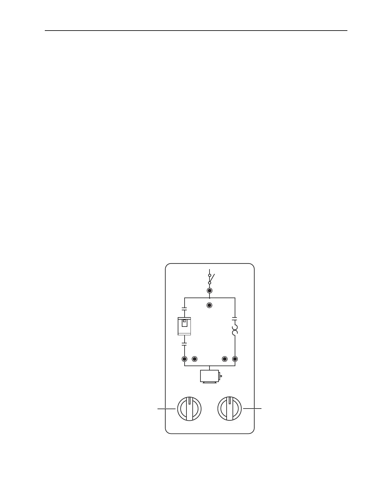
In addition, the Bypass Control Interface contains two selector switches.
Selector Switch 1 (SS1) determines the state of the DIC, DOC and BC
contactors. Selector Switch 2 (SS2) determines the source of control logic.
Figure 2.2 Bypass Control Interface
MOTOR
OFF
DRIVE
TEST
HAND
AUTO DRIVE BYPASS
MOTOR
BYPASS
RUN
BYPASS
TRIP
PURGE
DOC
DRIVE
OUTPUT
ENABLE
DIC
INTERLOCK
OPEN
BC
OL
FOR DRIVE STATUS
SEE DRIVE DISPLAY
DRIVE
READY
SS2
SS1

 Loading...


