H-2 Plate Drive Installation Instructions
Heatsink Thermal Capacity
The heatsink provided must have the thermal capacity to cool the drive
under worst-case loading conditions as well as for short duration
overload conditions in the application. Refer to Table A.C on page A-5
for estimated watts loss data.
Table H.B Required Heatsink Degrees C/W Capabilities
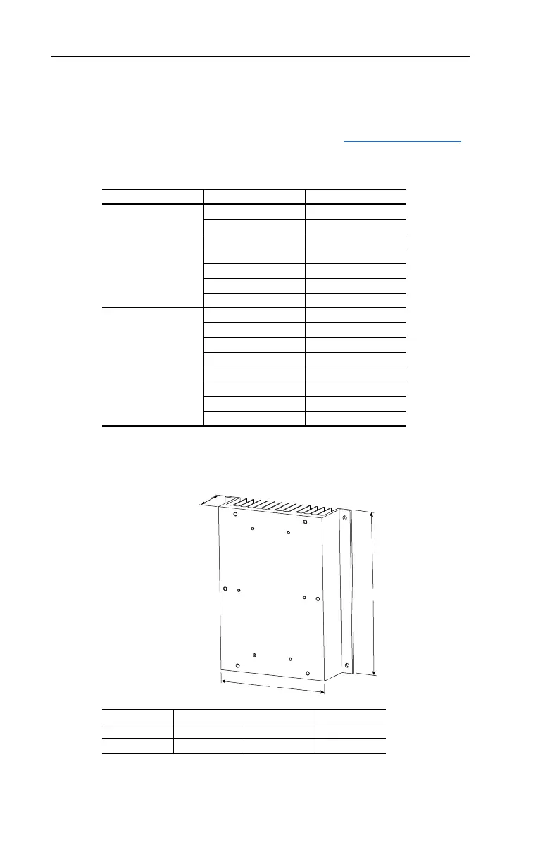
Figure H.1 Approximate Heatsink Dimensions for One Drive without Heatsink Fan –
Dimensions are in millimeters and (inches)
Plate Drive Input Voltage kW (HP) Heatsink °C/W Needed
230V AC 0.4 (0.5) 1.59
0.75 (1.0) 0.88
1.5 (2.0) 0.56
2.2 (3.0) 0.35
3.7 (5.0) 0.23
5.5 (7.5) 0.18
7.5 (10) 0.13
460V AC 0.4 (0.5) 2.06
0.75 (1.0) 1.17
1.5 (2.0) 0.73
2.2 (3.0) 0.47
3.7 (5.0) 0.26
5.5 (7.5) 0.25
7.5 (10) 0.20
11 (15) 0.13
Drive Frame Size A B C
B 214 (8.43) 250 (9.84) 63.1 (2.48)
C 300 (11.81) 325 (12.8) 138.2 (5.44)
C
B
A

 Loading...


