RS485 (DSI) Protocol C-3
Parameter Configuration
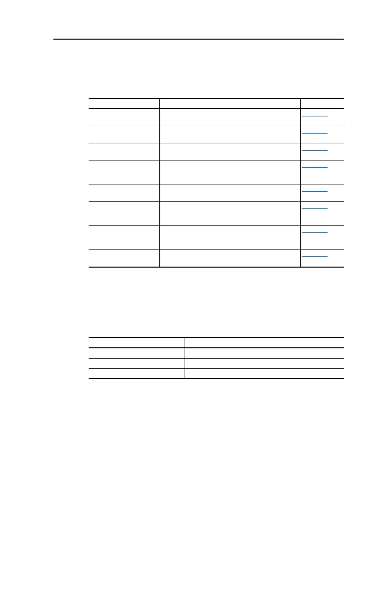
The following PowerFlex 40P parameters are used to configure the drive
to operate on a network.
Supported Modbus Function Codes
The peripheral interface (DSI) used on PowerFlex 40P drives supports
some of the Modbus function codes.
Important: Modbus devices can be 0-based (registers are numbered
starting at 0) or 1-based (registers are numbered starting at
1). Depending on the Modbus Master used, the register
addresses listed on the following pages may need to be
offset by +1. For example, Logic Command may be register
address 8192 for some master devices (e.g. ProSoft
3150-MCM SLC Modbus scanner) and 8193 for others
(e.g. PanelViews).
Parameter Details Reference
P036 [Start Source] Set to 5 “Comm Port” if Start is controlled from the
network.
Page 3-10
P038 [Speed Reference] Set to 5 “Comm Port” if the Speed Reference is
controlled from the network.
Page 3-12
A103 [Comm Data Rate] Sets the data rate for the RS485 (DSI) Port. All nodes
on the network must be set to the same data rate.
Page 3-34
A104 [Comm Node Addr] Sets the node address for the drive on the network.
Each device on the network requires a unique node
address.
Page 3-34
A105 [Comm Loss Action] Selects the drive’s response to communication
problems.
Page 3-34
A106 [Comm Loss Time] Sets the time that the drive will remain in
communication loss before the drive implements A105
[Comm Loss Action].
Page 3-34
A107 [Comm Format] Sets the transmission mode, data bits, parity and stop
bits for the RS485 (DSI) Port. All nodes on the network
must be set to the same setting.
Page 3-35
E207 [Comm Write Mode] Set to 0 “EEPROM” when programming drive.
Set to 1 “RAM only” to only write to volatile memory.
Page 3-52
Modbus Function Code (Decimal) Command
03 Read Holding Registers
06 Preset (Write) Single Register
16 (10 Hexadecimal) Preset (Write) Multiple Registers

 Loading...


