Troubleshooting 4-3
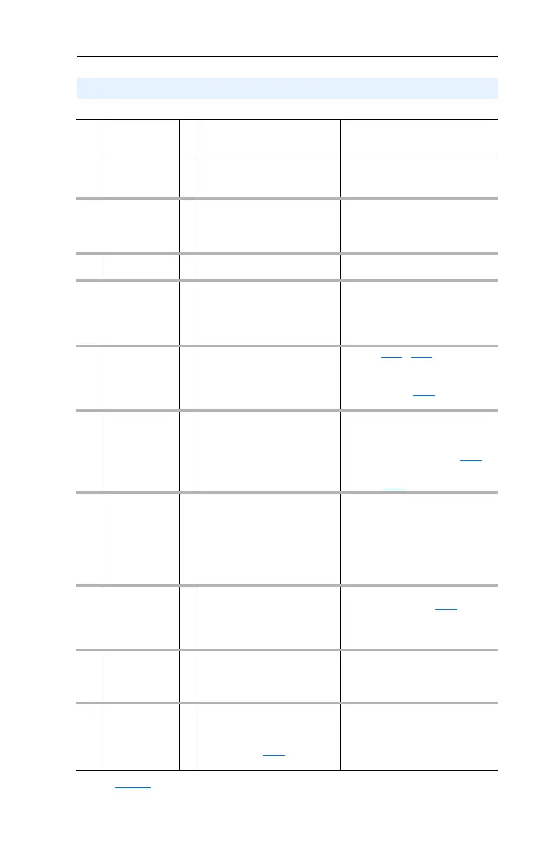
Table 4.B Fault Types, Descriptions and Actions
Fault Descriptions
No. Fault
Type
(1)
Description Action
F2 Auxiliary Input
➀
Auxiliary input interlock is open. 1. Check remote wiring.
2. Verify communications
programming for intentional fault.
F3 Power Loss
➁
DC bus voltage remained below
85% of nominal or single phase
operation detected.
1. Monitor the incoming AC line for
low voltage or line power
interruption.
2. Check input fuses.
F4 UnderVoltage
➀
DC bus voltage fell below the
minimum value.
Monitor the incoming AC line for low
voltage or line power interruption.
F5 OverVoltage
➀
DC bus voltage exceeded
maximum value.
Monitor the AC line for high line
voltage or transient conditions. Bus
overvoltage can also be caused by
motor regeneration. Extend the decel
time or install dynamic brake option.
F6 Motor Stalled
➀
Drive is unable to accelerate
motor.
Increase P039 - A067 [Accel Time x]
or reduce load so drive output
current does not exceed the current
set by parameter A089
[Current Limit
1].
F7 Motor Overload
➀
Internal electronic overload trip. 1. An excessive motor load exists.
Reduce load so drive output
current does not exceed the
current set by parameter P033
[Motor OL Current].
2. Verify A084
[Boost Select] setting
F8 Heatsink
OvrTmp
➀
Heatsink temperature exceeds a
predefined value.
1. Check for blocked or dirty heat
sink fins. Verify that ambient
temperature has not exceeded
40°C (104°F) for IP 30/NEMA 1/UL
Type 1 installations or 50°C (122°F) for
IP20/Open type installations.
2. Check fan.
F12 HW OverCurrent
➁
The drive output current has
exceeded the hardware current
limit.
Check programming. Check for
excess load, improper A084
[Boost
Select] setting, DC brake volts set
too high or other causes of excess
current.
F13 Ground Fault
➁
A current path to earth ground
has been detected at one or
more of the drive output
terminals.
Check the motor and external wiring
to the drive output terminals for a
grounded condition.
F29 Analog Input
Loss
➀
An analog input is configured to
fault on signal loss. A signal loss
has occurred.
Configure with A122
[Analog In
Loss].
1. Check parameters.
2. Check for broken/loose
connections at inputs.
(1)
See page 4-1 for a description of fault types.

 Loading...


