Programming and Parameters 3-27
Advanced Program Group (continued)
A082 [DB Resistor Sel] Related Parameter(s): P037
Stop drive before changing this parameter.
Enables/disables external dynamic braking.
The drive is able to provide full braking indefinitely. Braking power is limited by the external DB
resistor. When this parameter is set to 1 “Normal RA Res” and an appropriate resistor is used (see
selection Ta ble B.C
), the drive provides calculated resistor overload protection. However, the drive
cannot protect against a brake IGBT failure.
For more information on external dynamic brake kits, refer to the External Dynamic Brake Kit
Installation Instructions, publication RA-IN004.
Values Default: 0
Min/Max: 0/99
Display: 1
Setting Min/Max
0
1
2
3-99
“Disabled”
“Normal RA Res” (5% Duty Cycle) – Refer to Table B.C on page B-2
.
“NoProtection” (100% Duty Cycle)
“x%Duty Cycle” Limited (3% – 99% of Duty Cycle)
ATTENTION: A risk of fire exists if external braking resistors are not protected. The
external resistor package must be self-protected from over temperature or the protective
circuit shown in Figure B.7 on page B-12
, or equivalent, must be supplied.
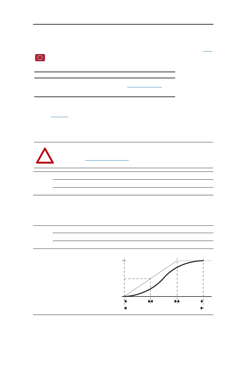
A083 [S Curve %]
Sets the percentage of acceleration or deceleration time that is applied to the ramp as S Curve. Time
is added, 1/2 at the beginning and 1/2 at the end of the ramp.
Values Default: 0% (Disabled)
Min/Max: 0/100%
Display: 1%
Example:
Accel Time = 10 Seconds
S Curve Setting = 50%
S Curve Time = 10 × 0.5 = 5 Seconds
Total Time = 10 + 5 = 15 Seconds
1/2 S Curve Time
2.5 Seconds
Total Time to Accelerate = Accel Time + S Curve Time
50% S Curve
Target
Target/2
Accel Time
10 Seconds
1/2 S Curve Time
2.5 Seconds

 Loading...


