20 Rockwell Automation Publication 6000-IN100A-EN-P - August 2020
Chapter 1 Drive Mechanical Installation
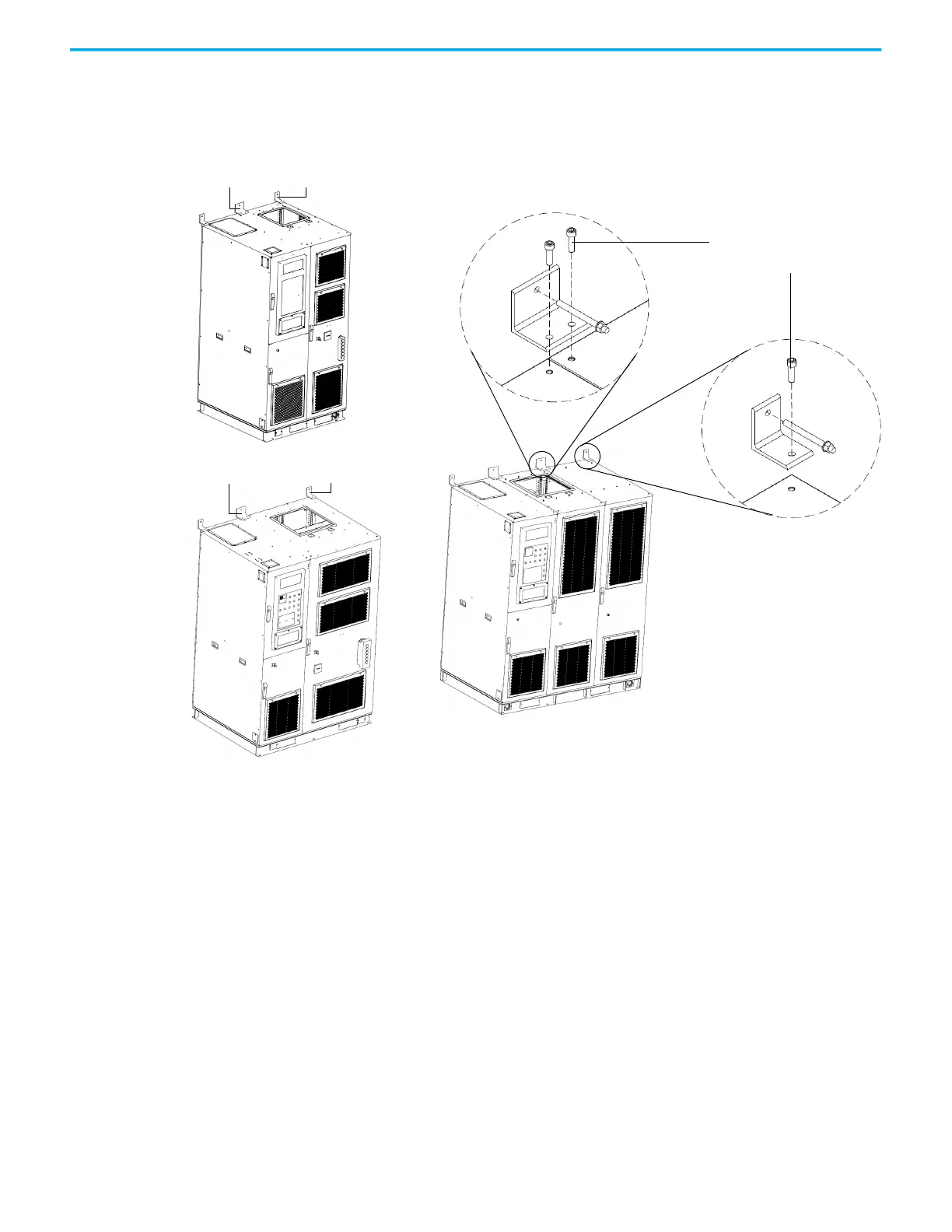
For condition 2 seismic installation, if there is no rear access available, the top
of the drive can be mounted to the wall rather than mounted to the floor at the
back of the cabinet. If there is a fan redundancy condition for frame 1 and
frame 2, then wall bracket B is not needed.
Install B-Frame Drives
For condition 1, installation of power cell cabinets, follow these instructions:
1. Disassemble the grounding busbar at the front of the cabinet.
2. Disassemble the anchor cover at the front of the cabinet.
Frame 1
Frame 3
Wall bracket B
Wall bracket A
Wall bracket B Wall bracket A
Wall bracket B Wall bracket A
Frame 2
M12xL35
Based on bracket thickness
of 11 mm (0.43 in.)
 Loading...


