46 Rockwell Automation Publication 6000-IN100A-EN-P - August 2020
Chapter 2 Drive Electrical Installation
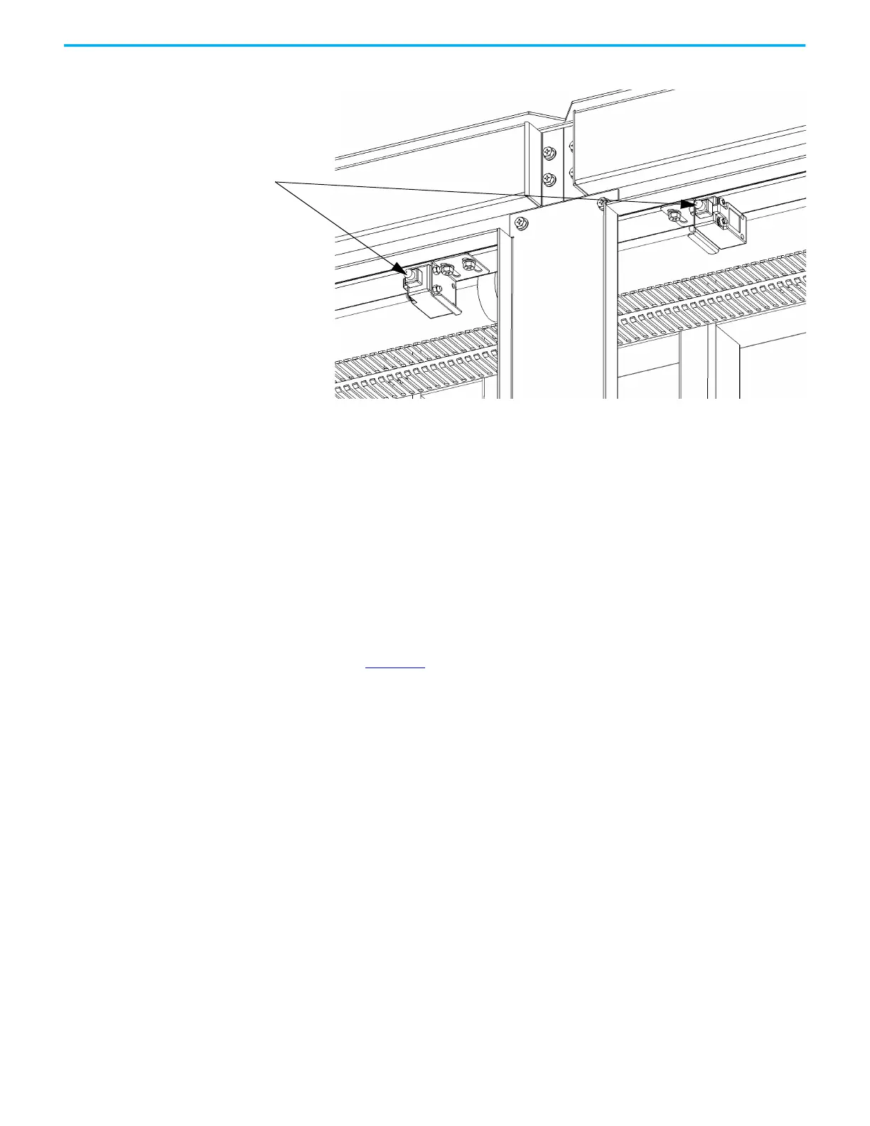
Figure 24 - Interlock for Cabinet Doors
When the doors of the Power Module/LV Control Cabinet or Isolation
Transformer Cabinet are not closed, when the drive is being maintained or
when the control power switch is not closed, the drive will not send a signal
allowing the input circuit breaker to close; this is wired as a permissive contact
in the input circuit breaker’s closing circuit so that the input circuit breaker
cannot close.
Wire Routing and Connection
The electrical safety interlock control signal wiring enters the drive through
the same opening as the control power wiring in the bottom of the LV Control
Cabinet (Figure 22
).
Door Position Limit Switch
 Loading...


