Rockwell Automation Publication 6000-IN100A-EN-P - August 2020 69
Appendix E
Line and Load Cable Sizes
Cable Sizes The data in the following tables are informative only; do not base final design
criteria solely on this data. Follow national and local installation codes,
industry best practices, and cable manufacturer recommendations. As cabling
methods can vary widely, maximum cables sizes do not account for the size of
the conduit hub.
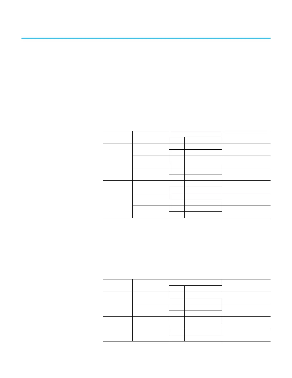
Table 16 - Line and Load Cable Sizes for A-Frame Drives (IEC)
Description
(Motor V/Freq.)
Drive Enclosure
Max. Size and No.
Incoming Cables: IEC
(1)
(2)
(3)
(1) Cable sizes are based on overall dimensions of compact-stranded three-conductor shielded cable (common for industrial
cable tray installations). Maximum sizing stated accounts for minimum rated cable insulation requirements and the next
higher-rated cable (that is, 8 kV is not commercially available in many areas of the world, therefore Rockwell Automation
provides an 8 kV (minimum rating) and a 15 kV rating, when applicable. Enclosure openings accommodate the thicker
insulation on the higher-rated cable. IEC ratings show the equivalent to the NEMA sizes. The exact cable mm
2
size that is
shown is not commercially available in many cases; use the next smaller standard size.
(2) Minimum cable bend radius recommendations vary by national codes, cable type, and cable size. Consult local codes for
guidelines and requirements. General relationship of cable diameter to bend radius is typically between 7x…12x (for example,
if the cable diameter is 1 in. [2.54 cm] the minimum bend radius could range between 7…12 in. [18.8…30.48 cm]).
(3) As cabling methods can vary widely, maximum cable sizes that are shown do not account for the size of the conduit hub.
Verify size of conduit hubs against the “Drive enclosure openings” shown.
Entry Opening mm (in.)
Maximum Line
Cable Sizes
3000V, 50 Hz
Top 435 x 300 (17.1 x 11.8)
203 mm² 6.6 kV/phase
Bottom 220 x 143 (8.7 x 5.6)
3300V, 50 Hz
Top 435 x 300 (17.1 x 11.8)
203 mm² 6.6 kV/phase
Bottom 220 x 143 (8.7 x 5.6)
4000/4160V, 50/60 Hz
Top 435 x 300 (17.1 x 11.8)
203 mm² 6.6 kV/phase
Bottom 220 x 143 (8.7 x 5.6)
Maximum Load
Cable Sizes
3000V, 50/60 Hz
Top 435 x 300 (17.1 x 11.8)
203 mm² 6.6 kV/phase
Bottom 220 x 143 (8.7 x 5.6)
3300V, 50/60 Hz
Top 435 x 300 (17.1 x 11.8)
203 mm² 6.6 kV/phase
Bottom 220 x 143 (8.7 x 5.6)
4000/4160V, 50/60 Hz
Top 435 x 300 (17.1 x 11.8)
203 mm² 6.6 kV/phase
Bottom 220 x 143 (8.7 x 5.6)
Table 17 - Line and Load Cable Sizes for A-Frame Drives (UL)
Description
(Motor V/Freq.)
Drive Enclosure
Max. Size and No. Incoming
Cables: IEC
(1)
(2)
(3)
Entry Opening mm (in.)
Maximum Line
Cable Sizes
2300/2400V, 60 Hz
Top 435 x 300 (17.1 x 11.8)
203 mm² (400 AWG)
6.6 kV/phase
Bottom 220 x 143 (8.7 x 5.6)
4000/4160V, 50/60 Hz
Top 435 x 300 (17.1 x 11.8)
203 mm² (400 AWG)
6.6 kV/phase
Bottom 220 x 143 (8.7 x 5.6)
Maximum Load
Cable Sizes
2300/2400V, 60 Hz
Top 435 x 300 (17.1 x 11.8)
203 mm² (400 AWG)
6.6 kV/phase
Bottom 220 x 143 (8.7 x 5.6)
4000/4160V, 50/60 Hz
Top 435 x 300 (17.1 x 11.8)
203 mm² (400 AWG)
6.6 kV/phase
Bottom 220 x 143 (8.7 x 5.6)
 Loading...


