102 Rockwell Automation Publication 750-IN100B-EN-P - July 2017
Chapter 5 Power Wiring
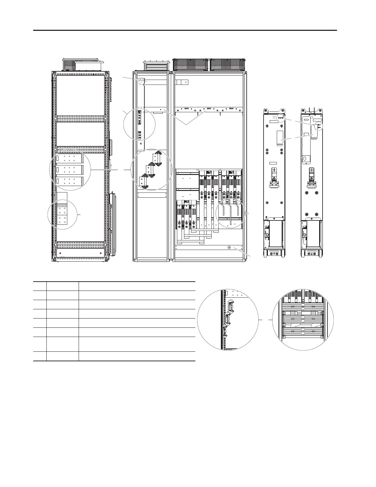
Bus Bar Locations
Figure 52 - Frame 8 and 9 Drives
Item Name Description
1 AC Link Connects AC circuit breaker to LCL fuse assembly
2 Testpoints DC+, DC- and R/L1, S/L2, T/L3 voltage testpoint sockets
3 Control Bus 120/240V and 24V AC control power supply connections
4 Input Power Bus R/L1, S/L2, T/L3 AC line input power connections
5 Motor Power Bus U/T1, V/T2, W/T3 motor connections
6 PE Grounding Bar Terminating point to chassis ground for incoming AC line and motor shield.
PE ground bar clamps, kit number SK-RM-GRNDCLMP-nn, are available.
7 Nameplate Power module and LCL filter module nameplate locations

 Loading...


