58 Rockwell Automation Publication 750-IN100B-EN-P - July 2017
Chapter 3 Prepare for Installation
Installation Site
Requirements
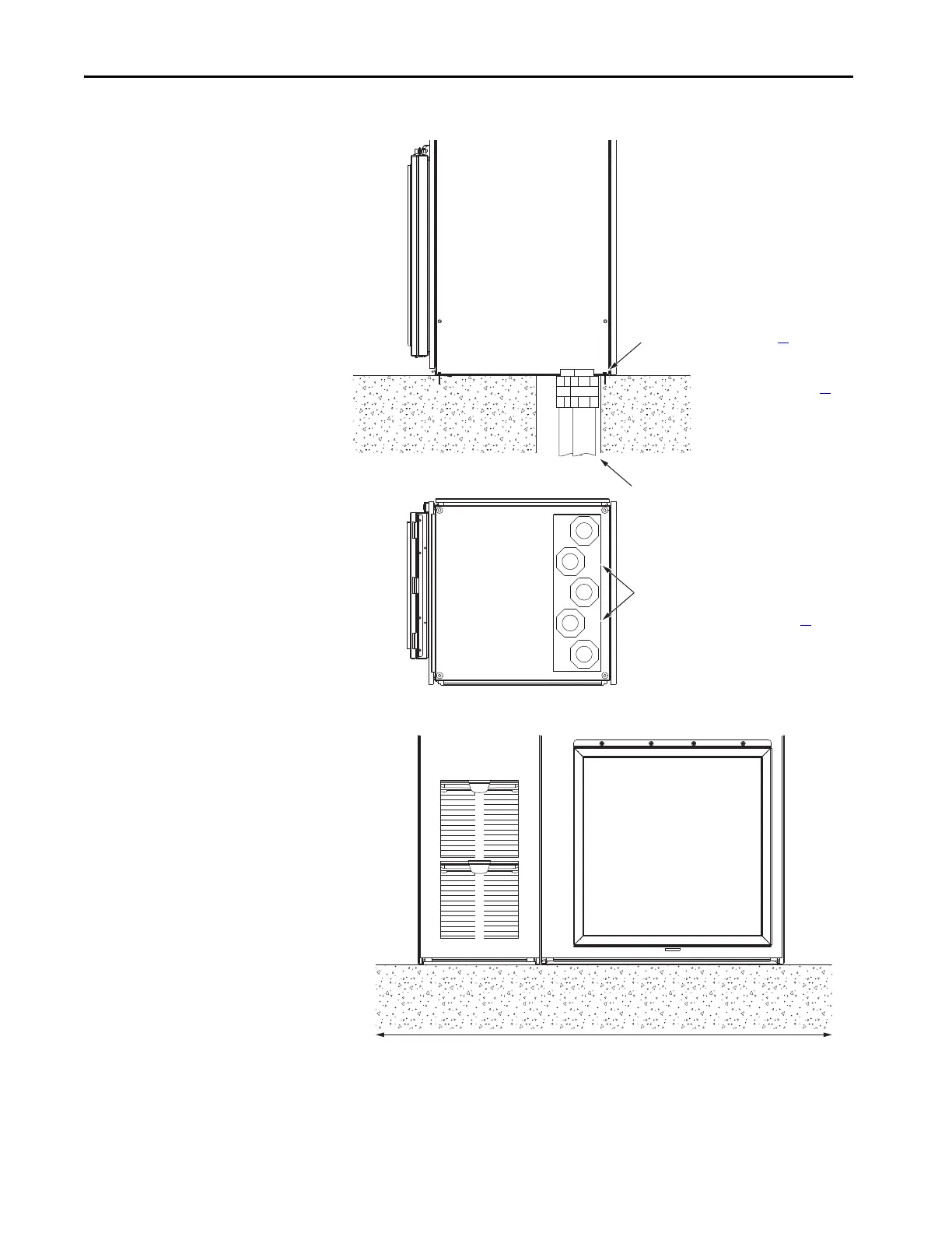
Figure 16 - Cross-section View of Cable Bottom Entry and Exit
Figure 17 - Mount on Level Surface
Install the product on a flat and level surface such that all enclosures in the line-
up are with ±0.25 mm (0.010 in.) vertical orientation.
Front Rear
Conduit
Mounting Hardware (See page 39
)
Mounting Surface (See page 31
)
Bottom
Recommended Cable Pattern, Power Bay
Use the locations marked on the plate.
See Approximate Dimensions on page 39
.

 Loading...


