Rockwell Automation Publication 750-IN100B-EN-P - July 2017 45
Prepare for Installation Chapter 3
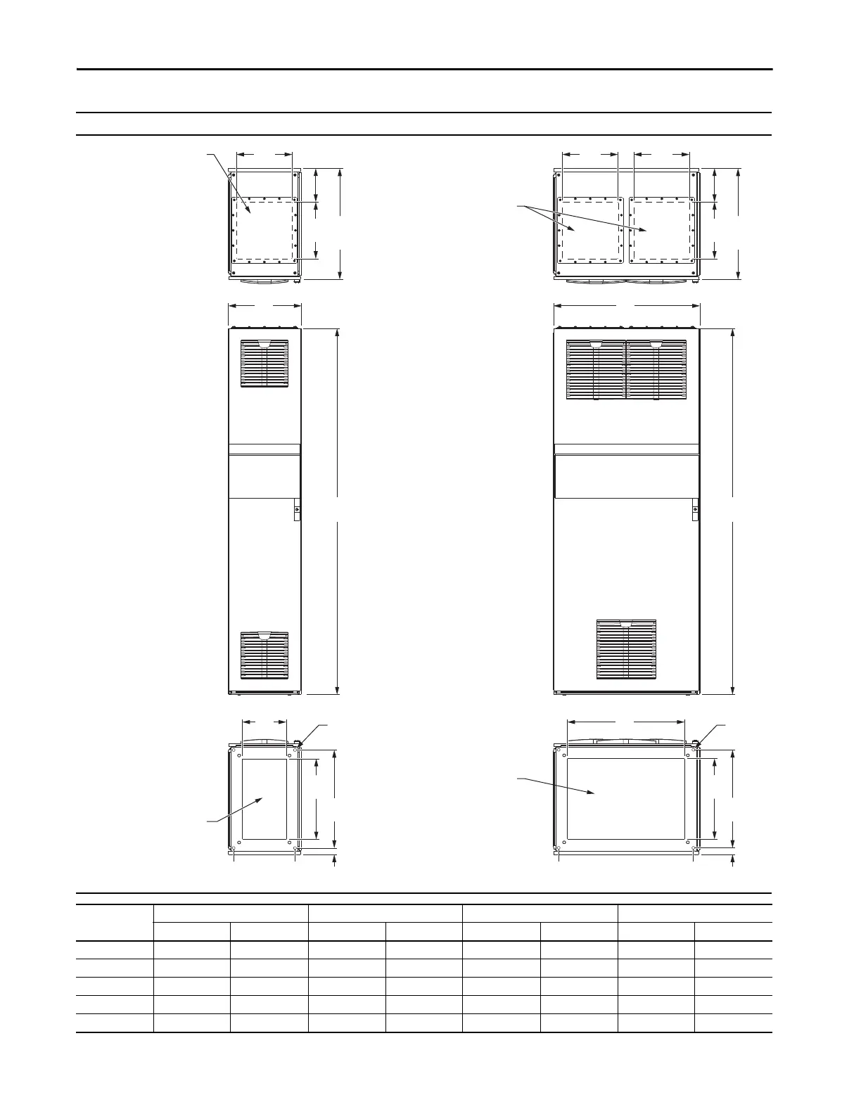
Drives Optional Entry and Exit Wire Bays Top, Front, and Bottom Views - Dimensions are mm (in.)
305
(12.0)
183
(7.2)
310
(12.2)
AB A
B
240
(9.4)
305
305
(12.0)
183
(7.2)
310
(12.2)
440
(17.3)
535
(21.1)
440
(17.3)
535
(21.1)
640
(25.2)
800
(31.5)
400
(15.7)
36
(1.4)
(26.6)
(1.4)
Input Power Cables - Top Entry
Motor Cables - Top Exit
Input Power Cables - Bottom Entry
Motor Cables - Bottom Exit
Input Power Cables - Bottom Entry
Motor Cables - Bottom Exit
Input Power Cables - Top Entry
Motor Cables - Top Exit
Mounting Holes
Mounting
Holes
Frame
Entry Bay – 400 (15.7) Wide Exit Bay – 400 (15.7) Wide Entry Bay – 800 (31.5) Wide Exit Bay – 800 (31.5) Wide
ABABABAB
8 – – 1200 (47.2) 1535 (60.4) – – – –
9 – – 2000 (78.7) 2335 (91.9) – – – –
10 400 (15.7) 65 (2.6) 3200 (126.0) 3535 (139.2) – – – –
11 – – – – 465 (18.3) 65 (2.6) 3800 (149.6) 4535 (178.5)
12 – – – – 465 (18.3) 65 (2.6) 4600 (181.1) 5335 (210.0)

 Loading...


