168 Rockwell Automation Publication 750-IN100B-EN-P - July 2017
Chapter 6 I/O Wiring
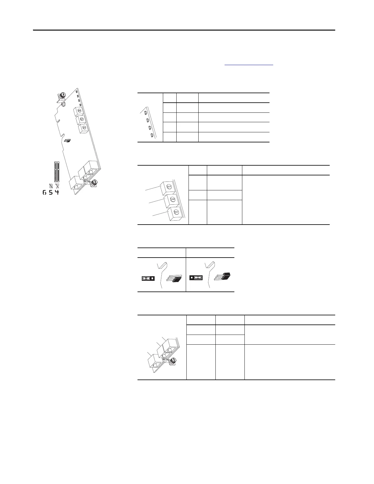
Dual-Port EtherNet/IP Option
Module
For complete information on the Dual-Port EtherNet/IP Option Module,
refer to the PowerFlex 20-750-ENETR Dual-Port EtherNet/IP Option
Module User Manual, publication 750COM-UM008
.
Table 46 - EtherNet Option Module LED Indication
LED Name Description
1 PORT DPI Connection Status
2 MOD Option Module Status
3 NET A Network Port 01 Status
4 NET B Network Port 02 Status
Table 47 - EtherNet Option Module Rotary Switches
Switch Name Description
1 HUNDREDS
Switch
Sets the node address of the option module.
2 TENS Switch
3 ONES Switch
Table 48 - J4 Jumper
Adapter Mode Tap Mode
Table 49 - Ethernet Connectors
Connector Name Description
1 ENET1 Ethernet RJ45 connection to the network.
2 ENET2
3 ENET3
(DEVICE)
Connection for the short Ethernet cable (provided
with option module) to the Ethernet port on the
PowerFlex 755 drive embedded EtherNet/IP
adapter. This is used only for CIP Motion data
transfer.
ADPTR

 Loading...


