EasyManuals Logo
Home>Allen-Bradley>Adapter>PowerFlex 755T

Allen-Bradley PowerFlex 755T Installation Instructions

Allen-Bradley PowerFlex 755T
192 pages
To Next Page IconTo Next Page
To Previous Page IconTo Previous Page
Page #68 background imageLoading...
Page #68 background image
68 Rockwell Automation Publication 750-IN100B-EN-P - July 2017
Chapter 4 Mechanical and Electrical Installation
PowerFlex 755TM Common Bus Inverters
This section lists the motor side inverters that you must remove to install the
product. For instructions on how to remove this component from the
enclosure, see Remove Power Module on page 73
.
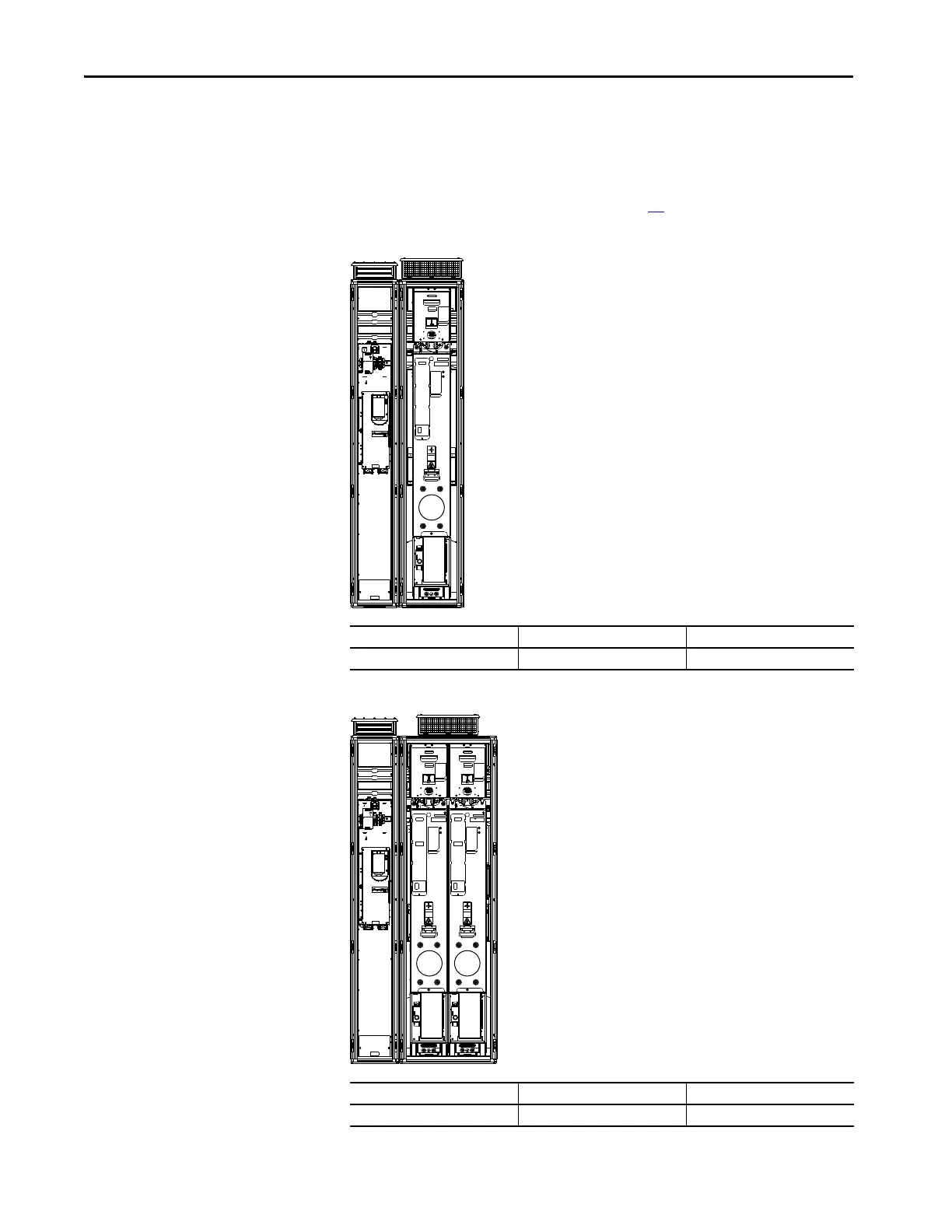
Figure 29 - Frame 8 Common Bus Inverter
Figure 30 - Frame 9 Common Bus Inverter
Module Type Remove Position No. Shipping Split Section
Motor side inverter M0 Section 1 of 1
Module Type Remove Position No. Shipping Split Section
Motor side inverter M0, M1 Section 1 of 1
M0
M1M0

Table of Contents

Other manuals for Allen-Bradley PowerFlex 755T

Questions and Answers:

Question and Answer IconNeed help?

Do you have a question about the Allen-Bradley PowerFlex 755T and is the answer not in the manual?

Allen-Bradley PowerFlex 755T Specifications

General IconGeneral
BrandAllen-Bradley
ModelPowerFlex 755T
CategoryAdapter
LanguageEnglish

Related product manuals