Rockwell Automation Publication 750-IN100B-EN-P - July 2017 39
Prepare for Installation Chapter 3
Recommended Cabinet
Mounting Hardware
Approximate Dimensions
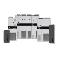
The following table lists the dimensional drawings provided in this section.
Frame Size Fastener Size Usage Notes
Frames 8 and
larger M12 (0.5 in.)
Threads into the cabinet mounting hole.
• Corner base/plinth system
• Structural steel system
Property Class 8.8 or better
(Grade 5 or better)
Frames 8 and
larger M10 (0.375 in.)
Passes through the cabinet mounting hole.
• Anchor bolt system
• Concrete screw system
Table 7 - Dimensional Drawing Index
Product Description Page
755TL and 755TR Drives Frame 8 Drives Top, Front, and Bottom Views 40
Frame 9 Drives Top, Front, and Bottom Views 41
Frame 10 Drives Top, Front, and Bottom Views 42
Frame 11 Drives Top, Front, and Bottom Views 43
Frame 12 Drives Top, Front, and Bottom Views 44
Drives Optional Entry and Exit Wire Bays Top, Front, and Bottom Views 45
755TM Bus Supplies Frame 8 Bus Supplies Top, Front, Bottom, and Side Views 46
Frame 9 Bus Supplies Top, Front, Bottom, and Side Views 47
Frame 10 Bus Supplies Top, Front, Bottom, and Side Views 48
Frame 11 Bus Supplies Top, Front, Bottom, and Side Views 49
Frame 12 Bus Supplies Top, Front, Bottom, and Side Views 50
Optional Entry Wire Bays Top, Front, and Bottom Views 51
755TM Common Bus
Inverters
Frame 8 Top, Front, and Bottom Views 52
Frame 9 Top, Front, and Bottom Views 53
Frame 10 Top, Front, and Bottom Views 54
Frame 11 Top, Front, and Bottom Views 55
Frame 12 Top, Front, and Bottom Views 56
Control Bay and Optional Exit Wire Bays Top, Front, and Bottom Views 57
 Loading...
