EasyManuals Logo
Home>Allen-Bradley>Adapter>PowerFlex 755T

Allen-Bradley PowerFlex 755T Installation Instructions

Allen-Bradley PowerFlex 755T
192 pages
To Next Page IconTo Next Page
To Previous Page IconTo Previous Page
Page #38 background imageLoading...
Page #38 background image
38 Rockwell Automation Publication 750-IN100B-EN-P - July 2017
Chapter 3 Prepare for Installation
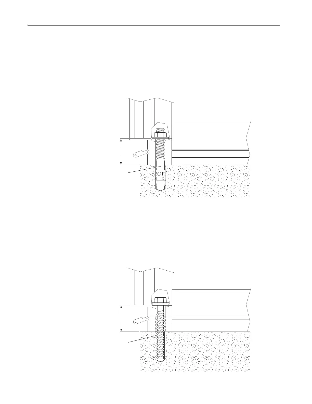
Anchor Bolt System
Enclosures can be mounted directly to a level concrete surface by using M10
(0.375 in.) anchor bolts.
The enclosures must be secured to the anchor bolts in all four corners by using
M10 nuts and lock washers.
Figure 14 - Anchor Bolt System Cross-section
Concrete Screw System
Enclosures can be mounted directly to a level concrete surface by using M10
(0.375 in.) concrete screws.
The enclosures must be secured by the concrete screws in all four corners.
Figure 15 - Concrete Screw System Cross-section
44 mm
(1.73 in.)
M10
(0.38 in.)
M10
(0.375 in.)
44 mm
(1.73 in.)

Table of Contents

Other manuals for Allen-Bradley PowerFlex 755T

Questions and Answers:

Question and Answer IconNeed help?

Do you have a question about the Allen-Bradley PowerFlex 755T and is the answer not in the manual?

Allen-Bradley PowerFlex 755T Specifications

General IconGeneral
BrandAllen-Bradley
ModelPowerFlex 755T
CategoryAdapter
LanguageEnglish

Related product manuals