166 Rockwell Automation Publication 750-IN100B-EN-P - July 2017
Chapter 6 I/O Wiring
• 24V DC ±10% must be supplied by a power supply that complies with
IEC/EN 61558-1.
For planning information, refer to the guidelines in Industrial Automation
Wiring and Grounding Guidelines, publication 1770-4.1
.
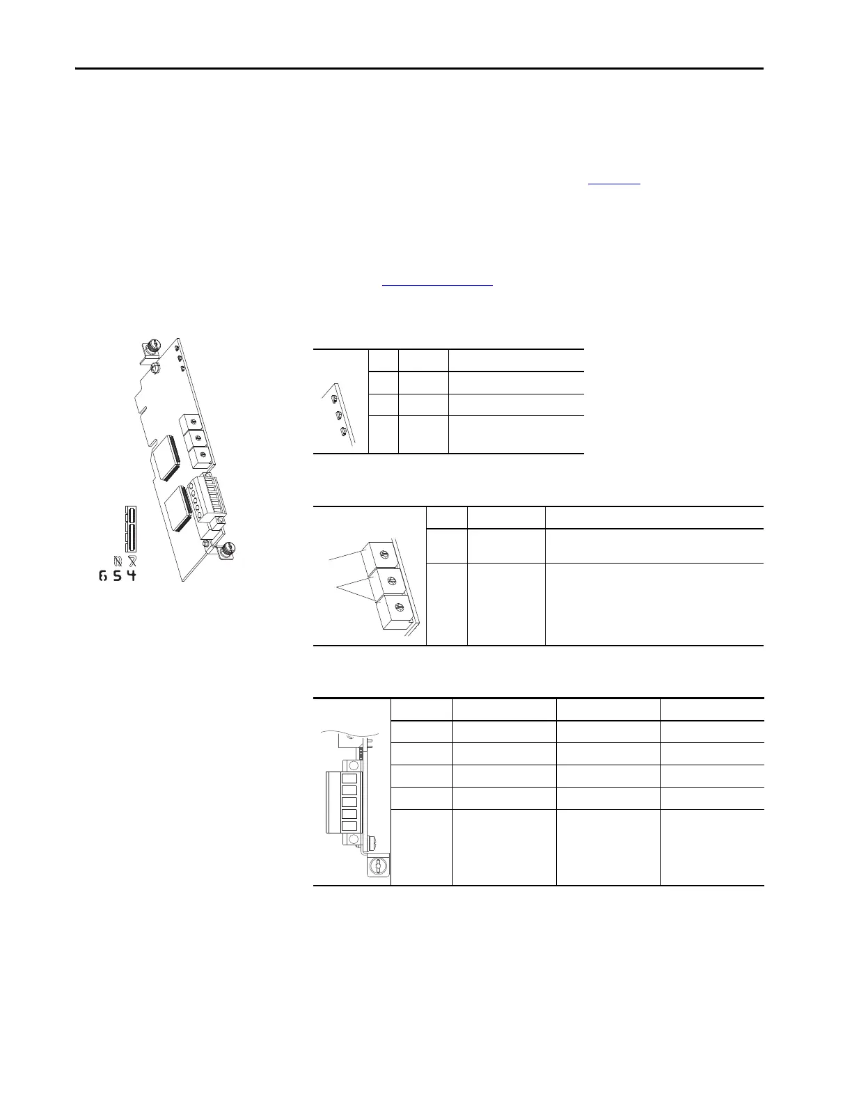
DeviceNet Option Module
For complete information on the DeviceNet Option Module, refer to the
PowerFlex 750-Series Drive DeviceNet Option Module User Manual,
publication 750COM-UM002
.
Table 40 - DeviceNet Option Module LED Indication
LED Name Description
1 PORT DPI Connection Status
2 MOD Option Module Status
3 NET A DeviceNet Status
Table 41 - DeviceNet Option Module Rotary Switches
Switch Name Description
1 Data Rate Switch Sets the DeviceNet data rate at which the option
module communicates.
2 Node Address
Switches
Sets the node address of the option module.
Table 42 - TB1 Terminal Designations
Terminal Color Signal Function
5Red V+ Power Supply
4 White CAN_H Signal High
3 Bare SHIELD Shield
2 Blue CAN_L Signal Low
1Black V- Common

 Loading...


