Rockwell Automation Publication 750-IN100B-EN-P - July 2017 141
I/O Wiring Chapter 6
Hardware Enable Circuitry
Each main control board has one digital input, Digital Input 0, that can be used
as a general purpose programmable input, or by removal of a jumper,
configured as a dedicated hardware enable, which is unaffected by parameter
settings.
• PowerFlex 755T - Digital Input 0 is found on TB1
To configure Digital Input 0 as a dedicated hardware enable, complete the
following steps.
1. Access the control pod as described beginning on page 138
.
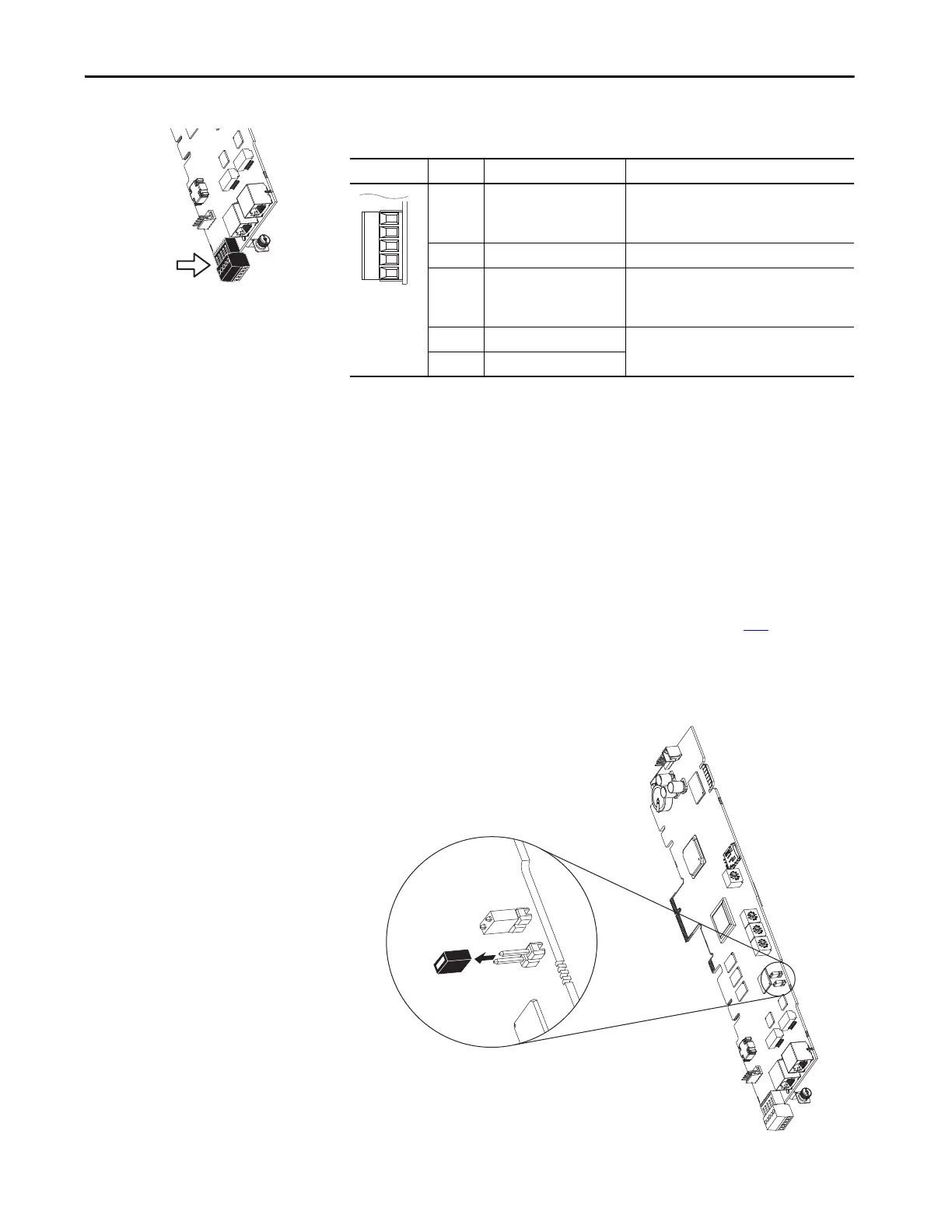
2. Locate and remove ENABLE Jumper on the Main Control Board (see
diagram).
Figure 67 - ENABLE Jumper Location
Table 21 - TB1 I/O Terminal Designations
Fixed I/O Terminal Name Description
Di 0ac Digital Input 0
120V AC (132V AC Max.)
Connections for AC power supply.
High State: 100…132V AC
Low State: 0…30V AC
Di C Digital Input Common Digital input common
Di 0dc Digital Input 0
24V DC (30V DC Max.)
Connections for DC power supply.
High State: 20…24V DC
Low State: 0…5V DC
+24V +24 Volt Power Connections for drive supplied 24V power. 150 mA
maximum
24VC 24 Volt Common

 Loading...


