40 Rockwell Automation Publication 750-IN100B-EN-P - July 2017
Chapter 3 Prepare for Installation
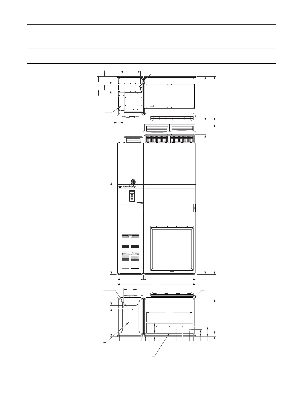
PowerFlex 755TL and 755TR Drives Approximate Dimensions
Frame 8 Drives Top, Front, and Bottom Views - Dimensions are mm (in.)
See page 45
for optional exit wire bay dimensions.
335 (13.2)
400 (15.7)
867.5 (34.2)
967.5 (38.1)
1135 (44.7)
0 (0)
451
(17.8)
45
(1.8)
709
(27.9)
1206
(47.5)
400
(15.7)
800
(31.5)
49
(1.9)
153
(6.0)
36
(1.4)
150
(5.9)
105
(4.1)
535
(21.1)
1407
(55.4)
IP21, UL Type 1
2132
(83.9)
2291
(90.2)
IP21, UL Type 1
676
(26.6)
Input Power Cables - Top Entry
Signal Cables - Top Entry
Dimensions same as bottom.
Motor Cables - Bottom Exit
(Plate is marked with recommended gland or conduit hole pattern.)
Power Bay
Input Bay
Signal Cables - Bottom Entry
Input Power Cables - Bottom Entry
Mounting Holes

 Loading...


