Rockwell Automation Publication 750-IN100B-EN-P - July 2017 47
Prepare for Installation Chapter 3
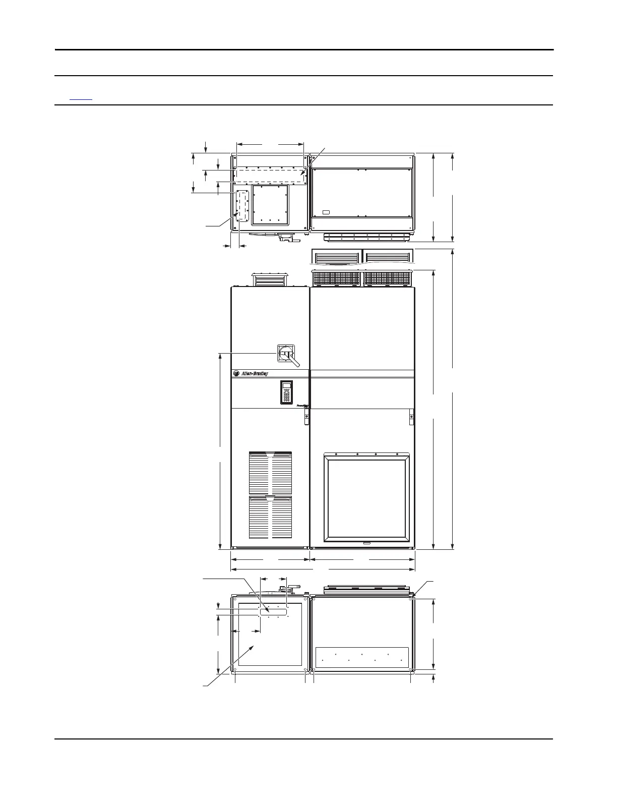
Frame 9 Bus Supplies Top, Front, Bottom, and Side Views - Dimensions are mm (in.)
See page 51 for optional entry wire bay dimensions.
0 (0)
535 (2.1)
451
(17.8)
45
(1.8)
200
(7.9)
600
(23.6)
1495
(58.9)
66
(2.6)
301
1406
(55.4)
800
(31.5)
36
(1.4)
535
(21.1)
IP21, UL Type 1
2132
(83.9)
2291
(90.2)
IP21, UL Type 1
676
(26.6)
Input Power Cables - Top Entry
Signal Cables - Top Entry
Dimensions same as bottom.
Signal Cables - Bottom Entry
Mounting Holes
Input Power Cables - Bottom Entry
Power BayInput Bay
 Loading...


