Rockwell Automation Publication 750-IN100B-EN-P - July 2017 57
Prepare for Installation Chapter 3
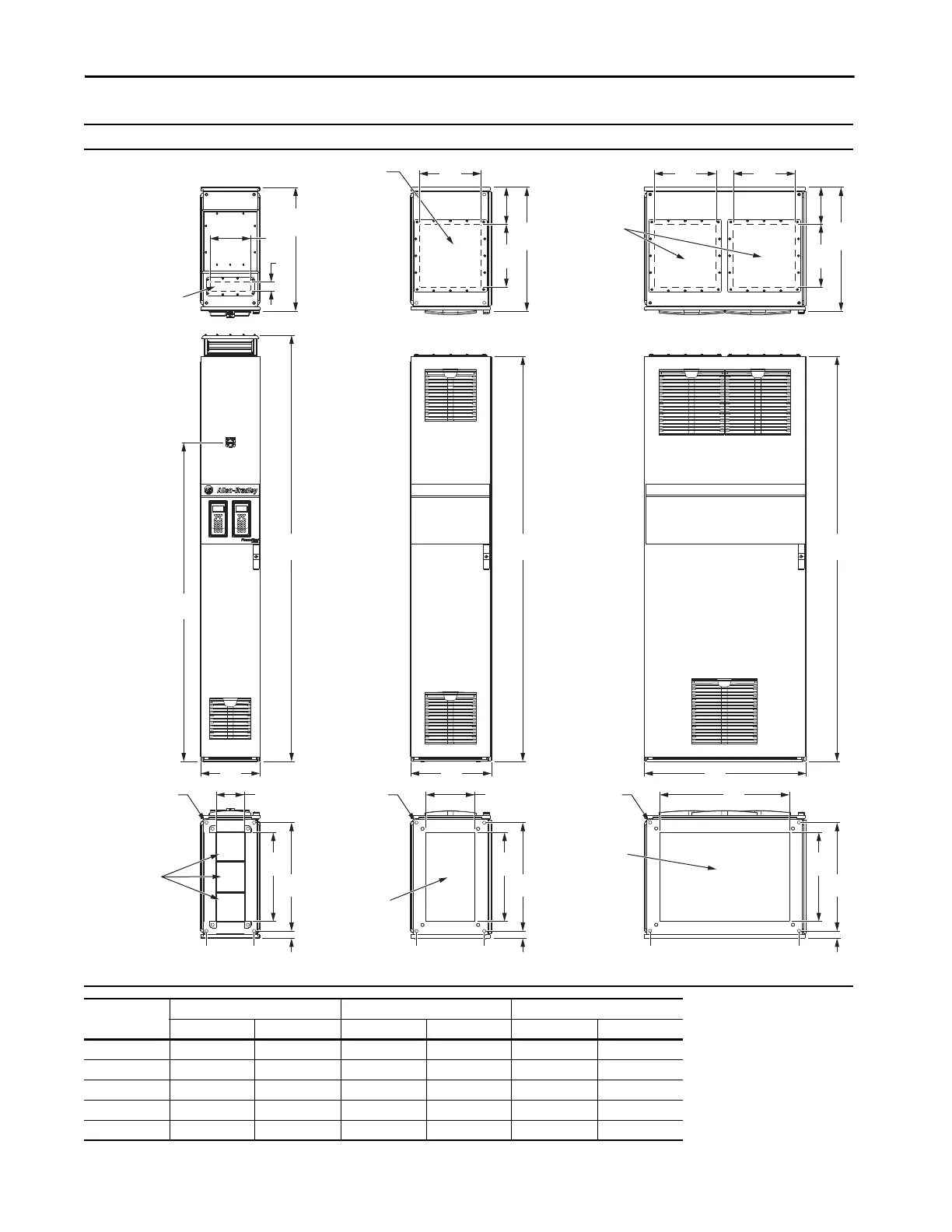
Common Bus Inverters Control Bay and Optional Exit Wire Bays Top, Front, and Bottom Views - Dimensions are mm (in.)
240
(9.4)
140
(5.5)
640
(25.2)
183
(7.2)
310
(12.2)
ABAB A
B
1571
(61.9)
200
(7.9)
535
(21.1)
440
(17.3)
45
(1.8)
36
(12.0)
183
(7.2)
310
(12.2)
800
(31.5)
400
(15.7)
300
(11.8)
2132
(83.9)
676
(26.6)
2000
(78.7)
676
(26.6)
2000
(78.7)
676
Motor Cables -
Top Exit
Motor Cables -
Top Exit
Motor Cables -
Bottom Exit
Motor Cables -
Bottom Exit
Signal Cables -
Bottom Entry
Signal Cables -
Top Entry
Mounting Holes Mounting Holes Mounting Holes
Wire Bay
Control Bay
Wire Bay
Frame
Control Bay – 300 (11.8) Wide Exit Bay – 400 (15.7) Wide Exit Bay – 800 (31.5) Wide
ABABAB
8 300 (11.8) 65 (2.6) 400 (15.7) 735 (28.9) – –
9 300 (11.8) 65 (2.6) 600 (23.6) 935 (36.8) – –
10 300 (11.8) 65 (2.6) 800 (31.5) 1135 (44.7) – –
11 300 (11.8) 65 (2.6) – – 1200 (47.2) 1935 (76.1)
12 300 (11.8) 65 (2.6) – – 1400 (55.1) 2135 (84.0)

 Loading...


