Chapter 2: Installation
41
Note
This system works with positive grounded or negative grounded DC
systems. E13
Warning
For centralized DC power connection, install only in a restricted
access area. E23
Note
A tray cable is required to connect the power source if the unit is
powered by centralized DC power. The tray cable must be a UL
listed Type TC tray cable and rated at 600 V and 90 degrees C, with
three conductors, minimum 14 AWG. E24
Warning
Circuit breaker is used as a disconnection device. To de-energize
equipment, shut down the circuit breaker and then disconnect the
input wire. E38
Warning
DC input shall be from a secondary source isolated from the mains
by reinforced insulation.
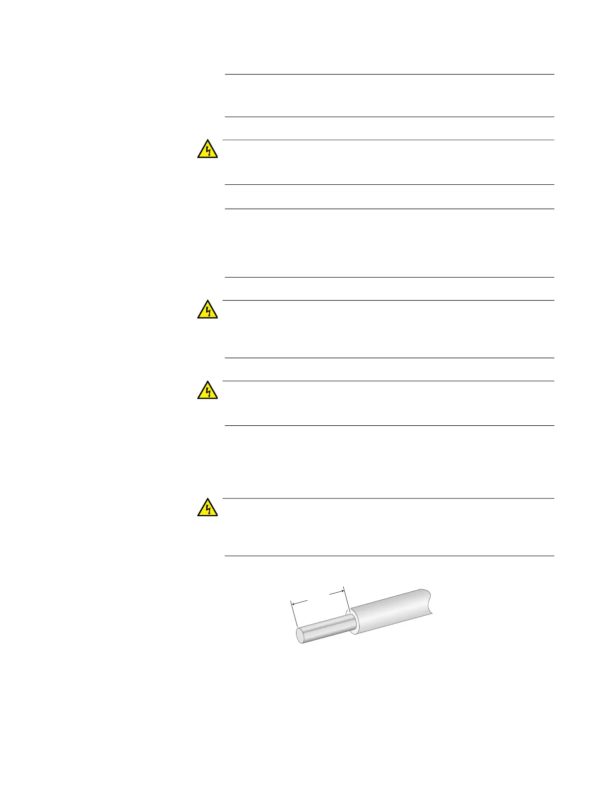
3. With a 14-gauge wire-stripping tool, strip the three wires in the tray
cable coming from the DC input power source to 8 millimeters ± 1
millimeters (0.31 inches ± 0.039 inches), as shown in Figure 21.
Warning
Do not strip more than the recommended amount of wire. Stripping
more than the recommended amount can create a safety hazard by
leaving exposed wire on the terminal block after installation. E10
Figure 21. Stripped Wire
8mm ±1mm
(0.31in. ±0.039in.)
 Loading...